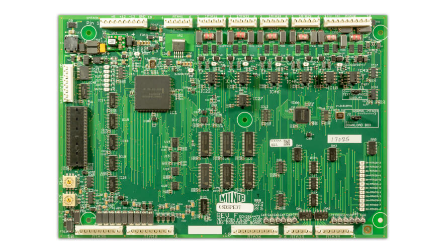
08BSPE3T Processor Board
Implementation Notes
1. Set the 12 volts at the power supply to 12.3VDC. The board generates its own 5 volts from the 12 volt supply.
When adjusting the 08PSS3401T power supply the 12 volt output and the 5 volt output move at the same time and are load dependent. That is to say that the card cage voltage is more important than the 12 volts into the 08BSPE3T.
2. Jumper settings:
- TXT/GPX -Typical Jumper Configuration -> set to GPX (for graphic displays) / TXT for 2 line text displays
- Download Box / MTA34 Normal -> set to "MTA34 Normal"
3. Connection changes
- All MTAs have noise reduction improvements.
- This board does not support parallel displays at MTA36 & 37 or VGA video cards.
- MTA41 was added for use with a “download box”.
4. No battery needed.
It does not need battery backup or supercapacitor to hold memory. It employs MRAM, magneto-resistive RAM, which holds data without backup voltage when power is turned off.
5. Serial port protection added
The 08BSPE3T processor board boasts a few added circuits that help protect the board against lightning strikes and system grounding issues.
Protection Circuit 1 helps discharge a lightning transient using a gas discharge tube and will shunt the circuit to ground in the event of a high voltage transient.
Protection Circuit 2 detects an overvoltage and overcurrent condition that could be due to grounding issues in the system.
Protection Circuit 3 handles smaller voltage transients using a transient blocking unit that opens the circuit to the transceiver chip in the event of small transients.
MTA41 & MTA34 share the LED labeled COM-MTA34. The other ports have their own LEDs.
The LED on MTA33 may be flashing so fast that it appears to be on constantly because that port is talking to a number of peripheral boards.
An ‘ON’ port LED indicates transmit.
Board failures can be misdiagnosed! If a user installs the board and has issues with communication, the board may be diagnosing a problem with the serial link. The grounding of the system should be checked first before declaring the board bad.
6. Download port changed to MTA 41
Port protection circuitry does not work with a download box. In light of this, another port has been added at MTA41 which is the same as MTA34 except without protection circuitry. The jumper needs to move so that the board can enable receive from the desired port, MTA41, (“download box”), or MTA34.
7. Board markings
- The input LEDs are marked with the corresponding MTA and pin number.
- The output LEDs are marked OUT1 through OUT6.
8. Other notes:
Some older software that does not use the outputs at MTA28, may not turn off the outputs in code, so the LEDs may be on.
The 5 volt and 3.3 volt LEDs just indicate that there is voltage present on that buss.
The Green RESET LED should be on steady. If it is flashing, then the board is not running, and it is constantly trying to reboot. This usually indicates a bent pin on the software EPROM.
Revision E and F 08BSPE3T boards are equivalent and were the first board revisions shipped in production. Rev G is also equivalent; the board change is only to accommodate a new package for the MRAM chip. The silicon die inside the package is the same; the chip manufacturer just discontinued one of the packages.
The 08BSPE3T is a perfect replacement for the 08BSPE2T in every application except for machines which use parallel displays or VGA video cards.
If you are updating a Dryer from 08BSPE2T to a 08BSPE3T there is one wiring change.

