The paddle wheel flow meter is used in monitoring the quantity of water being use by a machine. Whereas a
Burkert Mag Meter is used to gauge and quantify flow during Pulse Flow, and a
Gemu Flow Meter is used to gauge and typical counter flow rates in machines before Pulse Flow.
Milnor Part Number:
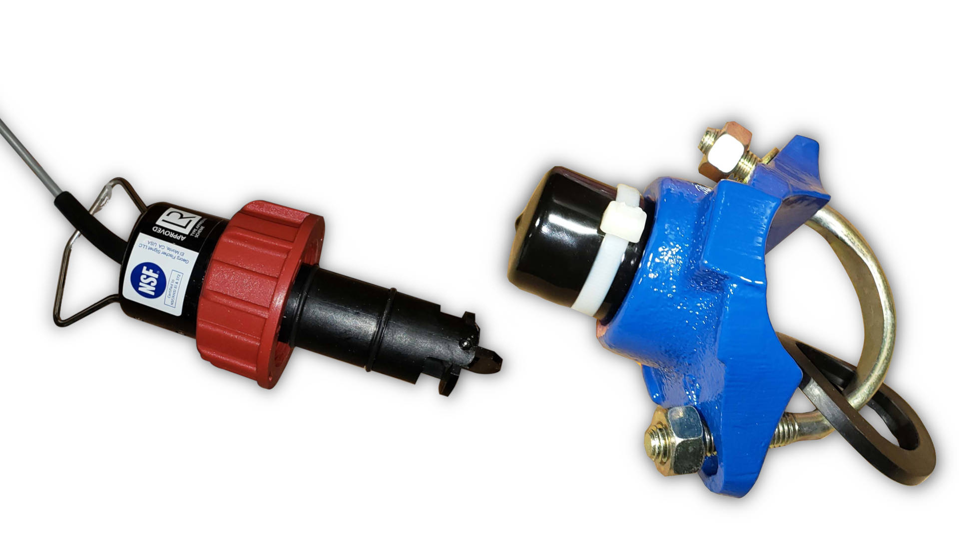
30F515 Paddle wheel flow meter (left)
30F519A Flow meter saddle for 2" pipe (right)
(other numbers that may be in the assembly)
30F518 - SIGNET S/S PIPE TEE 1.5" (lower left)
30F516 - ADFOR 2.5" + 3" SADDLE SIGNET (lower center)
5R3A1ECI - NPT SADDLE 3X1.25 CI 300# SB (lower right)
Most Mentor CBW's have paddle wheel sensors for water consumption data collection. If you have a Mentor then there is no reason to read further.
Directions for installation of paddle wheel flow sensors (if you do not have one already)
REQUIRED PARTS
- flow meter 30F515
- Harness for adding power for new board
- connector saddle 30F520
- signal conditioner board 08BNDFST
- high speed 816 board 08BS816BHT
One each of these parts is required for each flow sensor installed.
REQUIRED TOOLS
- Variable speed drill to cut 1 7/16 hole
- Basic hand tools
PLACING THE FLOW SENSOR
See Figures 1 for instructions to select a location for the flow sensor. The piping that the flow meter mounts to must have fully developed turbulent flow (See Figure 3). For optimum performance, the flow sensor should mount to the pipe at an angle 45 degrees off of vertical (See Figure 2).
STEPS FOR INSTALLATION
1. Drill a 1 7/16" hole in the selected location on the pipe.
2. File the area around the hole to remove chips.
3. Insert the connector saddle, including the rubber gasket, into the hole and clamp it down tightly.
4. Insert the adapter and the flow sensor. Hand tighten the flow sensor to the holder. !!Do not use tools to tighten the sensor - Hand tighten only!!
Flow sensor cable will be wired to the signal conditioning board. The purpose of the board is to amplify the signal. This board will be wired to the 8/16 board of the nearest available CBW module. NOTE: If you are installing more than one flow sensor, each must be wired to separate 8/16 boards in adjacent CBW modules.
5. Mount the signal conditioning board near the 8/16 board to which you intend to run the input.
6. Connect the frequency out from the sensor (red wire) to pin #5 of MTA62.
7. Mount the frequency return (black wire) to pin #4 of MTA62.
8. Ground pins #3 and #4 to MTA62.
On the output of the signal conditioning board (MTA61),
9. Wire pins #9 and #10 to ground.
10. Wire MTA61 pins #3 and #4 to 5 volts positive.
11. Wire MTA61 pin #2 to MTA62 pin #6 on the 8/16 board.
CALIBRATING THE FLOW SENSOR FOR MILTRON SYSTEMS
Water data is viewed on the F03 page in the let column "Fresh Water" heading of the module to which you have wired the sensor. The counts column and the total fresh water usage gallons should be counting.
You must enter an initial count per gallon figure in the L page of the Miltron. This count is temporary and will be replaced by the calculated figure that will be determined in the next few steps.
1. Go to the L page of the module to which the sensor is wired.
2. Press ESC twice.
3. Turn the key to program. The cursor will be on the left side of the screen above the bit number. This position is called "neutral."
4. Hit the BACKSPACE key and line feed to FR CPG.
5. Enter a figure from this chart:
Pipe Size = 1 1/4" US Gals = 8827 Liters = 2337
Pipe Size = 1 «" US Gals = 5994 Liters = 1587
Pipe Size = 2" US Gals = 3554 Liters = 941
Pipe Size = 3" US Gals = 1463 Liters = 387
6. Hit return and ESC out.
7. Turn the key to RUN.
8. Configure the L page for each module that has a flow sensor installed.
9. To calibrate the count per gallon, run a know quantity of water through the flow sensor and record the total number of counts.
10. Divide the total number of gallons by the total number of counts to get counts per gallon.
To calibrate the machine while it is operating,
11. Run the machine until all temperatures and levels are satisfied.
12. Observe the flow rate through the sight glass on the sensor.
13. Record the flow when it reaches a steady rate.
14. Go to the F03 page on the Miltron.
15. Enter the mini password (the middle letter of your 3 letter password) and press CTRL B. This will zero the numbers on the page with the exception of the counts per gallon constant.
16. Record the number of counts in the Fresh Water column in one minute. Repeat this several times to get an average count.
17. Divide the average counts per one minute by the flow rate (recorded earlier). This is the new counts per gallon constant.
18. Enter the new counts per gallon constant on the L page under FR CPG on each module to which a flow sensor is wired.
BECAUSE THE WATER DATA IN THE MILTRON IS IN VOLATILE MEMORY, IT IS RECOMMENDED THAT YOU RECORD THE WATER DATA AT THE END OF THE WORKING DAY AND ZERO THE WATER DATA AT THE BEGINNING OF MORNING STARTUP.
NOTES:
CBW software version 00108 or later is required for correct water flow metering.
Report Generator software version 02018 or later is required for water flow data to be passed to MILDATA. Water data appears on the Machine report. The data also appears on the Machine by Formula report for Report Generator version 02019 and later.

