Overview
If your Graphic display (flat panel with part number beginning with EC66FPD) comes up blank or with a faint vertical line, the display memory is totally blank. When the displays are shipped from the supplier, the memory is blank. If they get shipped without being programmed by Milnor, the internal memory is blank. This is a normal condition and the memory for the display must be downloaded from the machine processor.
To resolve this issue follow this procedure;
- Check the peripheral boards are talking, serial lights blinking. This ensures that the processor is operating.
- Press the "LEVEL" button.
- Allow the machine at least 3 to 4 minutes for the display memory to be updated.
The memory download includes the graphics backgrounds that become part of the formatted displays. While running or programming the data that changes is constantly updated by the machine software while the graphics data is stored in the display itself.
There are 2 versions of firmware for the display, DCUL3 and DCUL7. See the chips on the display board for a sticker with this data. These are not compatible. So, if changing the display, the machine software MUST be updated before you download data to the display. Otherwise the data is locked and you cannot update the data in the field easily. The update requires flashing the display from a PC and some software from Milnor that is not publicly available.
If the display has a suspected hardware problem read this...
The Graphics display panel began usage on Milnor Washer Extractors in 2005. The device has a 4" x4" display that shows graphics in the diplay and allows a larger view of formulas, program data and operations data while the machine is running.
If the display is not working, understand the following information to make an informed decision on repairing or replacing the device.
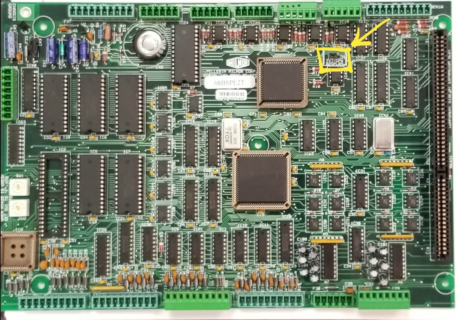
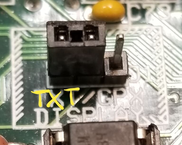
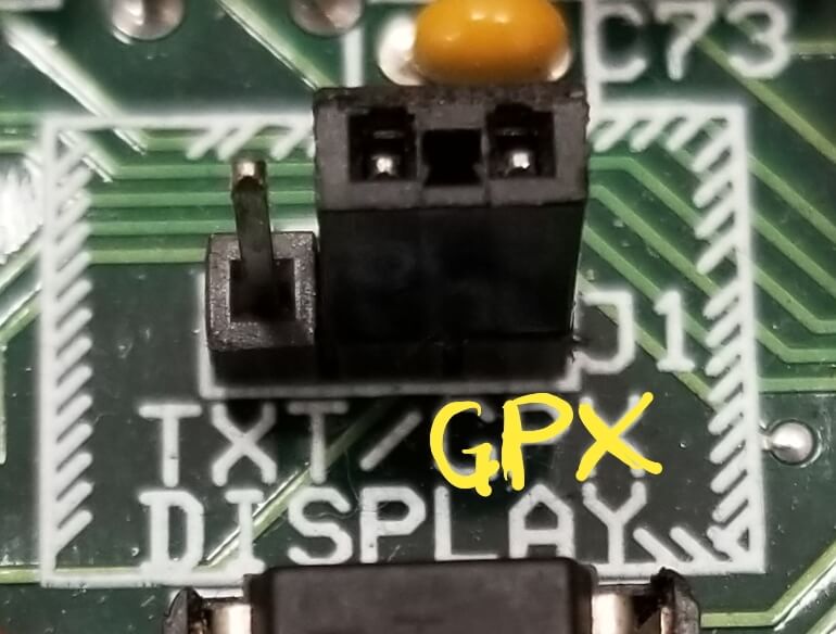
The processor card must have the TXT/GPX jumper put on for GPX. This display works with processor 08BSPE2T and later. The GPX symbol stands for the Graphics Display panel. A "Display Firmware Not Compatible" error can also be caused by the jumper being on the TXT side instead of GPX.
Graphic Display Jumper Location:
Graphic Display Set To Text:
Graphic Display Set to Graphics:
When the machine powers up and 12 volts DC is available to the display board, the display will actually show 2 horizontal bars, one at the top and one at the bottom. If there are no horizontal bars displayed then there is either no power or the backlight is not working.
You will probably not see anything on the display if the back light is not working.
The display assembly is made of 3 parts, the Flat panel, the driver board and the 485 to 232 converter board (This was a AT3 board which was replaced by the AT4, pn 08BSAT4AT, then replaced by 08BSEDIFAT)
The AT3 board has an inverter on it to convert 12VDC to about 300 VAC. This is what makes the display light up. It will probably light you up too, if you touch the wrong terminals.
There is a 2 pin connector that supplies the 300VAC to the Flat Panel. You can measure this value with an AC voltmeter. (The meter may load down the AC signal from the AT3 or AT4)
The inverter that converts the 12vdc to 300 VAC is the same size as a stack of 3 dominos. A couple have failed as of 070206. If this is the case the AT3 board can be replaced alone and make the display work again. So, measure the input at 12VDC and if no output is measured at 300VAC then the inverter is bad. (AT3 can be replaced with AT4, 08BSAT4AT)
The few voltage checks may prove a 12VDC supply issue rather than a display board failure.
In addition...
If your color graphic display is blank it is possible that the display contrast has been turned down by accident. If the contrast is at its lowest level the display will appear blank.
To adjust display brightness
From the manual menu display:
The F1 button increases the brightness of the display. Press repeatedly to make the display progressively brighter.
The F2 button decreases the brightness of the display. Press repeatedly to make the display progressively darker
A note on supply voltage to the display, specifically on washer extractors...
The DCUL3 is obsolete and replaced with DCUL7 (EC66FPDVA). The software also has to change to WUWEMK6A.
As for the connections - the connections physically should be the same - however some early machines are using 5 volts and the display has to be 12 volts. You would pull the old display and look at the white 6 pin connector with 6 wires ( 1- 4 serial, 5 ground, and 6 is voltage). This may be hanging on a harness. Either way check the voltage on wire 6 and see if it is 12 or 5 volts. If 12 volts the new display should install with no changes. If it is 5 volts you would need to move this wire and connect it to a 12 volt bus in the back of the machine.
Overview of downloading the data to the display.
The attachment shows a switch panel with graphics display panel for a split pocket washer extractor. If the display is similar on your machine this data applies.
Graphics display and machine software (installed in the processor board) need to be "in sync". For Mark 6 machines and later if the display firmware and the machine firmware are not "in sync" then the machine will prompt to download the appropriate data to the display on power up. This can happen if you update the machine software or change language in configure. Pressing the "level button" will initiate the download. Once the download is finished the machine will automatically proceed to the select formula screen.
All the text data, animation, and color objects are stored in the graphics display flash memory. The machine software uses "hooks" to call these items to display. If the display data is not "in sync" with the machine software then you may see "garbage" on the screen making it impossible to diagnose. All the display data is embedded in the machine software eprom. The software checks the display version on power up and forces a download if the display and software are incompatible.
If connector problems cause a data download disruption...
In addition to machine software and display incompatibility, a bad connection from the display, ST3, to MTA30 causes communication problems leading to a blank screen.
It could be that upon installing a new display and downloading the firmware to the display from the PE2T, bad wiring interrupts the download.
If the download is interrupted in the middle it is usually unrecoverable other than with the DCUterm program. See "Bricked"
A similar problem can occur in normal operation when the operator powers on the machine and the processor board detects a DCU firmware incompatibility. If the communication is not satisfactory, the PE2T would send a screen to the display, that would show "incompatible firmware press LEVEL" on a Washer or on a PRESS it would show "press ENTER". This would attempt to initiate a download of firmware to the DCU. If the wiring is bad the download could be interrupted resulting in a blank screen.
What if my display is "bricked"?
The download from the wrong version of Milnor software essentially "bricks" the display. A DCUL3 display downloaded with software for a DCUL7 or vice versa will cause the issue.
If you display is bricked, check out this article :
Video - How to Unbrick a DCUL-7 Display. If that doesn't fix your issue try the second method below.
The recovery of a bricked display is possible with a program called DCU Term (only available from Milnor) and a cable that allows connection to the display board from a PC. This uses a 4 pin Molex cable and a serial connection on the other end. After clearing the memory in the display with a PC, the Milnor processor board can then download necessary data. Alternately, you can return the display to Milnor for recovery.
If choosing to investigate the recovery option you will need a display board to PC cable which can be made with 10YMTA04BP and a USB to 485 converter available from MILNOR. Twisted 18 gauge wire can make the connections. The attached zip file contains the data needed. The info in the documents is dated as the connectors have changed, but the info is otherwise correct. The software was used on 32 bit Windows machines. 64 bit Windows machines have not been tested.


