Replacing Power Supply 08PSS3401T (for Retrofit Kits 08PSS3401N and 08PSS3401X)
The power supply provided with this kit is a 40 watt unit with linear +5VDC, +12VDC and -12VDC outputs, used on many Milnor machines. Although it replaces a power supply of the same general specifications, you will probably need to make certain modifications to accommodate the new power supply. If you received kit 08PSS3401N, you will likely need to make mechanical modifications. No matter which kit you received, you may also need to make electrical modifications. The possible modifications include:
Install new bracketry (08PSS3401N)
If you received kit 08PSS3401N, your machine probably has an older style power supply. If so, you will need to install the bracketry and use the wire harnesses supplied with the kit to accommodate the newer style power supply.
Install a metal oxide varistor (MOV)
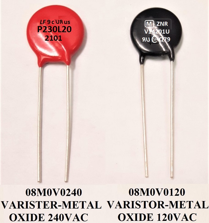
The MOV (part number 08M0V0240 (240V) or 08M0V0120 (120V) - all zeros no o's) is supplied with both kits and must be installed across the new power supply's incoming power conductors, on any machine. This component protects the power supply from damage due to electrical spikes.
Install a regulating resistor
The resistor is supplied with both kits but is used only on machines that don't already have this resistor on the processor board. It must be installed across the new power supply's 5 volt DC output conductors, as shown in Figure 2.

Please verify that all components listed in the kit parts list were supplied. Contact the Milnor Parts Department if any items are missing.
WARNING 1 : Electrocution and Electric Shock Hazards
You can be electrocuted or seriously injured if you come in contact with 240 VAC or 120 VAC (depending on model) power, which is present in the processor electric box.
- Lock out/tag out power to the machine while replacing the power supply.
- Use caution while testing and adjusting the new power supply with power on.
- Do not attempt these procedures unless qualified and authorized.
CAUTION 2 : Component Damage Hazard
Electronic components will fail if not properly connected. Warranties can be voided if failure to follow these procedures results in damaged components.
- The ground trace on the power supply must be connected to the chassis of the machine, as explained herein.
- The regulating resistor must be installed if the processor board does not already contain this component and omitted if it does, as explained herein.
- Carefully read and understand this instruction before proceeding.
1. Mounting the New Power Supply
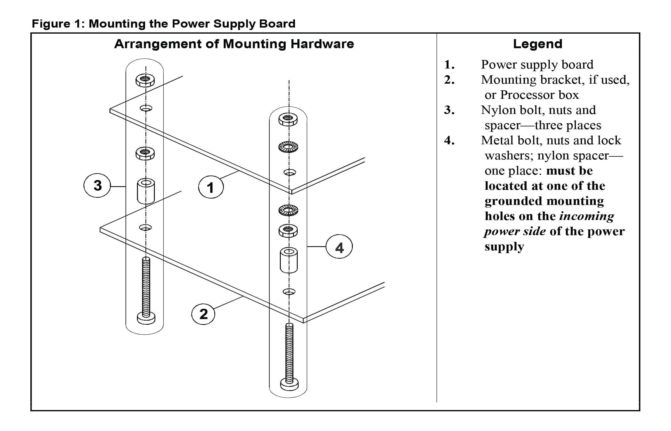
Depending on the original equipment, new bracketry may be needed to accommodate the new power supply. Whether or not this is the case, the new power supply board must be mounted as shown in Figure 1.
1.1. Kit 08PSS3401X (for Newer Machines)
Merely swap out the old with the new power supply. Make certain that a good connection is established between the ground trace on the power supply board and the machine chassis, as shown in Figure 1. If the new power supply is not a direct match for the old, contact the Milnor factory.
1.2. Kit 08PSS3401N (for Older Machines)
Various mounting brackets are supplied with this kit. If your original equipment does not accommodate the new power supply, select the hardware that permits you to locate the new power supply about where the old one was. The mounting hardware supplied with the kit attaches the power supply to its mounting bracket. Hardware to attach the mounting bracket to the machine is not supplied with the kit. Use any appropriately sized bolts, nuts and lock washers or self-tapping screws. Recommended hardware installation is as follows:
- If a mounting bracket will be used, determine how it will be attached. Carefully prepare the Processor box as required to accept it, but do not install it until step 3.
- Attach the power supply to the mounting bracket or directly to the Processor box, as shown in Figure 1. One of the four bolts supplied with the kit is metallic. This bolt must be placed in one of the two grounded mounting holes (hole through a metallic trace on the power supply's printed circuit) on the incoming power side of the power supply. Ensure that the power supply is grounded to the mounting bracket or Processor box by scraping the paint from around the hole on the bracket or box with the metallic bolt. Be sure the metal nut and lock washer do not touch any other component.
- If a mounting bracket was used, install this assembly in the Processor box. Ensure that the mounting bracket is grounded to the Processor box by scraping the paint from around one pair of adjoining mounting holes on the bracket and the Processor box.
2. Determining Whether to Install or Omit the Regulating Resistor
The purpose for the regulating resistor is to ensure that the power supply has a certain minimum load. This is necessary for the power supply to be able to maintain the specified output. Machines that use this power supply have processor boards with Milnor part numbers beginning with “08BSP...”, “08BN...” or “08BH...” You will need to read the part number printed on your processor board (usually on a sticker affixed to the board). If the part number begins with “08BSP...”, your control system uses peripheral boards connected to the processor board via a serial interface. In all probability, the regulating resistor should not be used because the peripheral boards provide sufficient load (see Section 2.1). For the other controller types, the resistor is needed but may or may not already be present on your machine (see Section 2.2).
2.1. Machines With “08BSP...” Processor Boards
On these machines, omit the regulating resistor. However, in rare cases, a machine with this type of board may have too few peripheral boards to provide a sufficient load for the power supply. If, after replacing the power supply, your machine experiences resets (as explained in Section 4), contact Milnor Customer Service to determine if the problem is likely due to insufficient load on the power supply. If this is determined to be the case, you will need to install the resistor, as explained in Section 3.
2.2. Machines With “08BN...” and “08BH...” Processor Boards
The regulating resistor is built into newer processor boards. If the processor on your machine does not have this resistor on board, install the one included with the kit, as explained in Section 3. Otherwise, omit the resistor. The following are three ways to determine whether the resistor is present on your machine. Because it is very important to either install or omit the resister as appropriate, double-check by using at least two of the methods explained below.
- By observation—You may be able to identify the regulating resistor on your processor board by comparing it to one of the pictures in Figure 2.
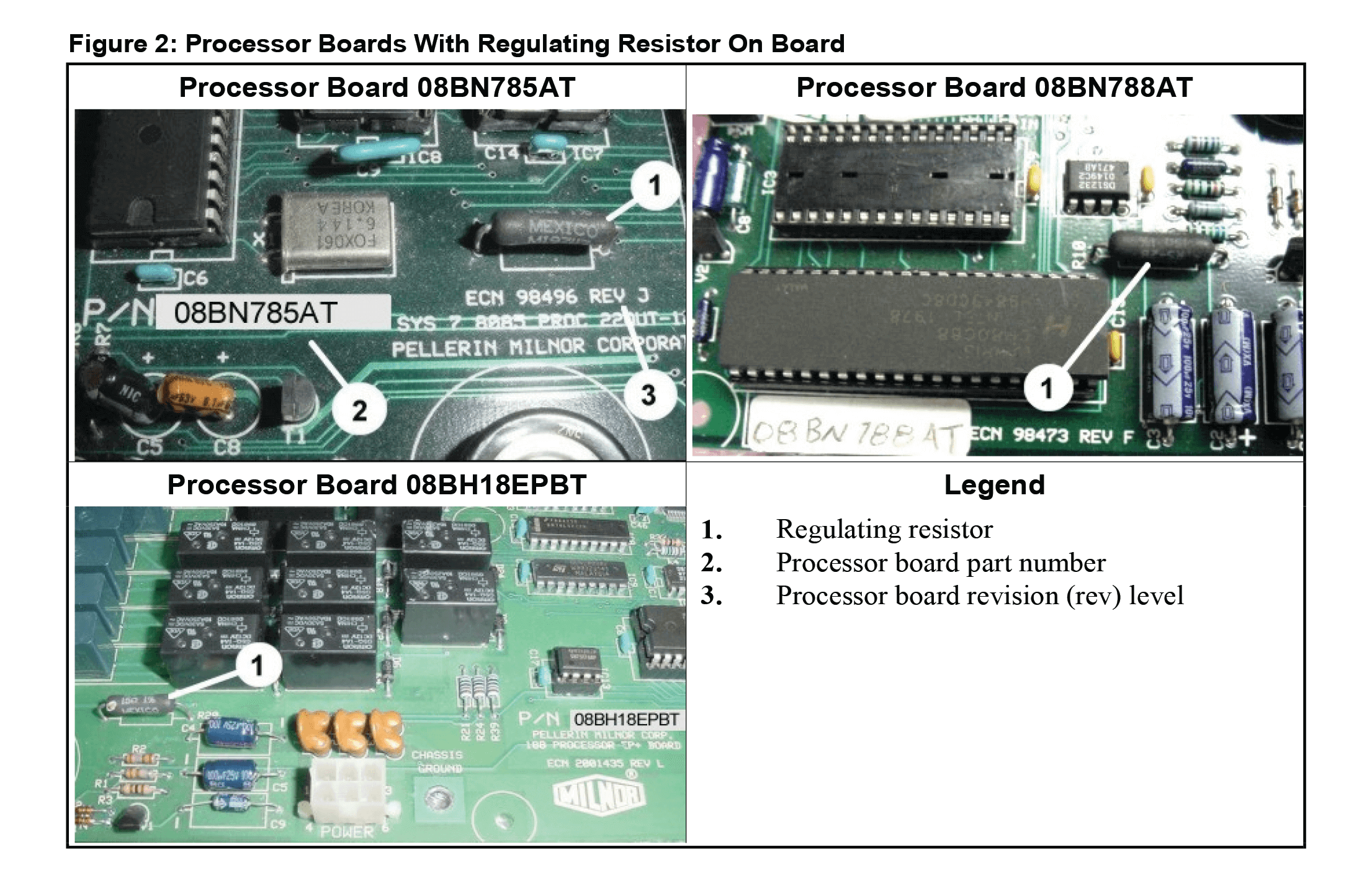
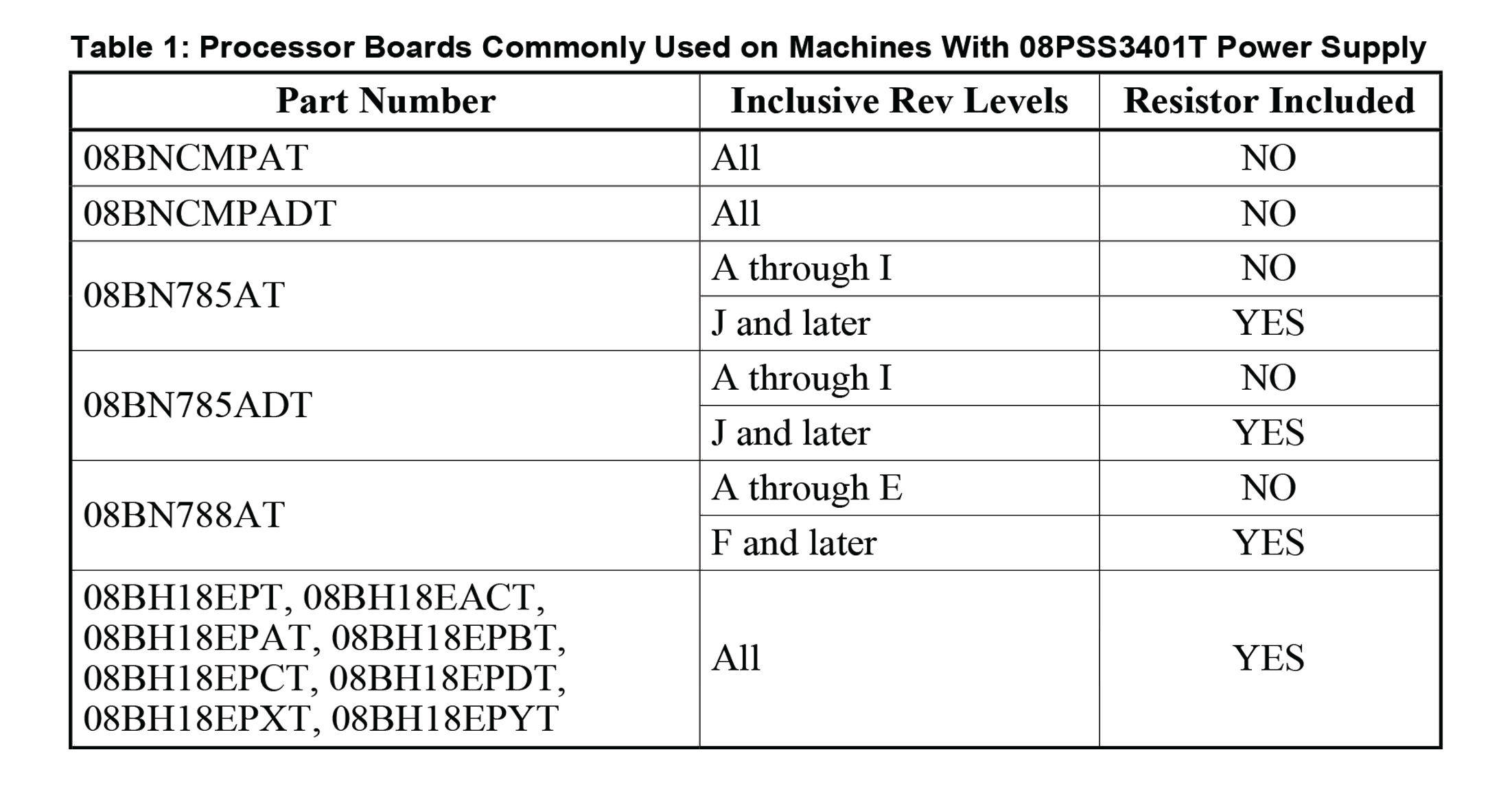
- By processor board number and revision level—As shown in Figure 2, the processor board part number and revision (rev) level are printed on the board. Compare the part number and rev level of your processor board with the list in Table 1 to determine if your board has the resistor on board:
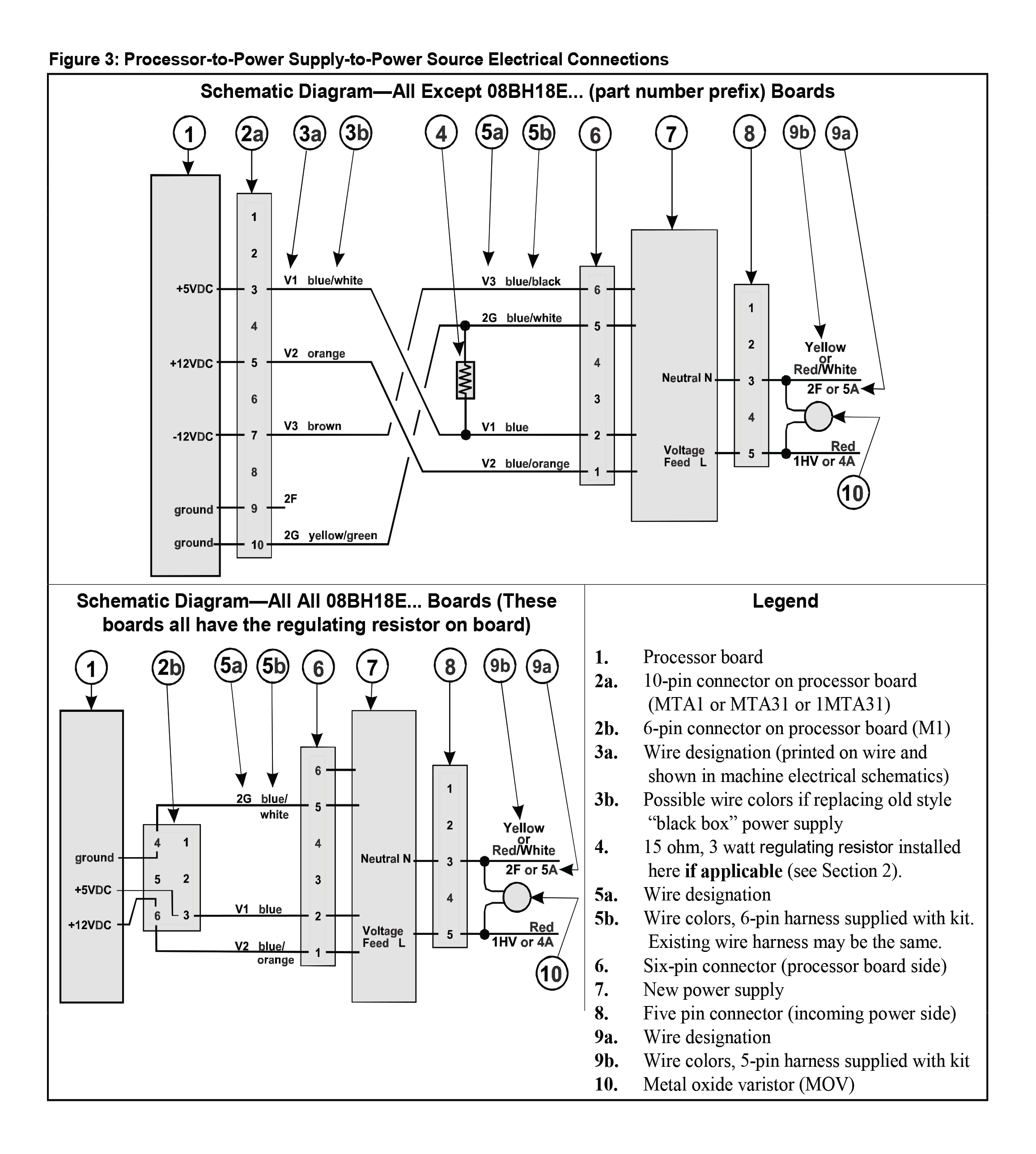
- By measuring the resistance across the board—Disconnect the processor board from the power supply if this has not already been done. With an ohmmeter, measure the resistance across +5VDC and signal ground (pins 3 and 10 on the 10 pin connector, as shown in Figure 3). The resistor is connected in parallel with +5VDC circuit so if it is present, the resistance will measure approximately 15 ohms. If the resistor is not present, the reading will be much higher (over 1000 ohms).
3. Electrical Connections
The procedure for making electrical connections will vary somewhat with the kit supplied, type of machine, and the type of power supply being replaced. However, except possibly for wire color codes, the schematics shown in Figure 3 cover all situations. (Older machines may use different wire color codes, but the pin numbers will be the same as shown in this figure.) Consult the original schematic manual for wire colors on an older machine or contact the Milnor factory.
CAUTION 3 : Component Damage Hazard
Wire V3, which supplies -12VDC, is not used on certain machines (e.g., machine models ending in C4A, M4A, or M4E, as well as machines that use neither an A/D (analog-to-digital), nor a D/A (digital-to-analog) board). If unused, terminate this wire with a wire nut to prevent shorting.
Observing caution statement 2 and referring to Figure 3, make the electrical connections appropriate for your machine, as follows.
3.1. Kit 08PSS3401X (for Newer Machines)
Once the power supply has been swapped out and the electrical connectors plugged into the new power supply, all that remains is to install the MOV, and if applicable, the resistor.
- Install the MOV across the power supply's incoming power conductors, as shown in Figure 3. Splice the leads of the MOV as close as possible to the connector on the power supply side. The MOV is not polarity-sensitive.
- If you determined in Section 2 that the regulating resistor supplied with the kit must be used, install it as shown in Figure 3. Again, splice the leads of the resistor as close as possible to the connector on the power supply side. The resistor is not polarity-sensitive.
CAUTION 4 : Component damage hazard
When in use, the regulating resistor can become hot enough to melt wire insulation. Ensure that any wires are well clear of the resistor.
3.2. Kit 08PSS3401N (for Older Machines)
3.2.1. Power Supply-to-Power Source Connections—All Machines
Even if the old connector (the one that was attached to the old power supply) matches the one supplied with the kit, cut it off to facilitate installing the MOV. The MOV must be installed across the power supply's incoming power conductors as shown in Figure 3. Splice the new harness and the leads of the MOV to the wires from the power source using two of the white caps provided with the kit. Match the wires as shown in Figure 3. The incoming power conductors are polarity-sensitive but the MOV is not.
3.2.2. Processor-to-Power Supply Connections If Resistor Supplied With the Kit Is Used (see Section 2)
Attach this resistor across wires 2G (blue/white, ground) and V1 (blue, +5VDC) on the six-pin wire harness supplied with the kit, using two of the white caps provided. Cut off the old connector (the one that was attached to the old power supply) and splice the new harness to the wires from the connector on the processor board, matching the wires as shown in Figure 3.
3.2.3. Processor-to-Power Supply Connections If Resistor Supplied With the Kit Is Omitted (see Section 2)
If your original processor-to-power supply wire harness has the same six-pin connector and same color wires as the one supplied with the kit, you may simply attach the existing connector to the new power supply. If not, cut off the old connector (the one that was attached to the old power supply) and splice the new harness to the wires from the connector on the processor board using two of the white caps provided, matching the wires as shown in Figure 3.
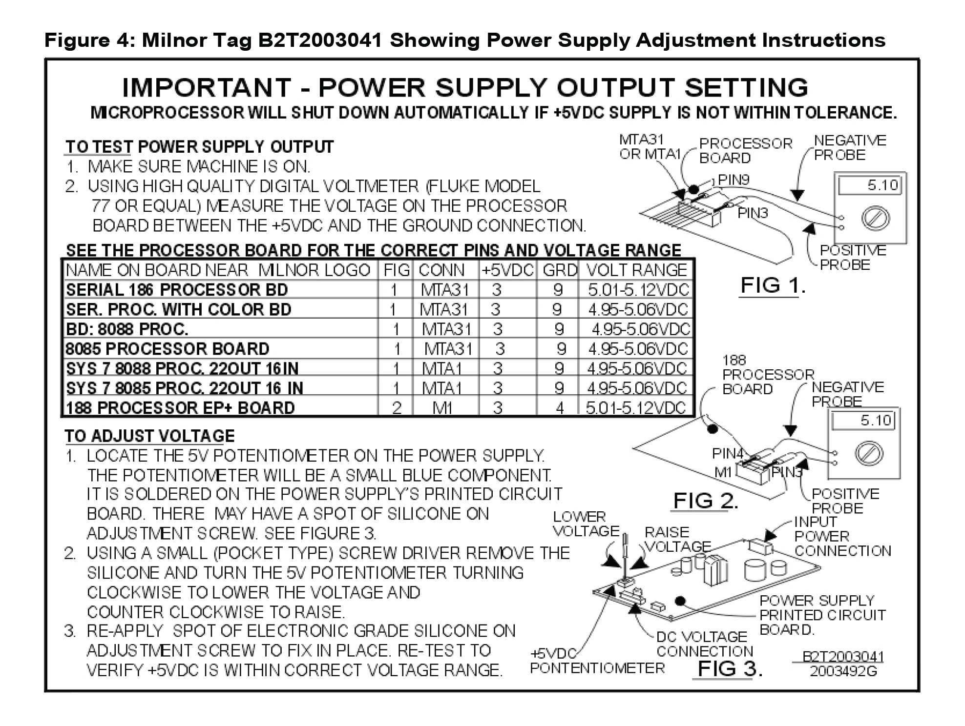
4. Setting the +5VDC Output Voltage The +5VDC output voltage must be maintained within a narrow range.
If the voltage varies from this range, this can cause the processor board to reset, resulting in interruptions in operation. A potentiometer (pot) is provided on the power supply board for adjusting this voltage. The adjustment instructions are provided on tag B2T2003041, supplied with the kit and shown in Figure 4. Affix this tag to the inside of the processor box so that it will be handy if the adjustment procedure must be repeated in the future. As explained in the tag, the +5VDC output voltage must be set using the pot, then the pot adjustment screw secured with a drop of electronics grade silicon. When performing these adjustments, observe the precautions given in warning statement 1 and caution statement 5.
CAUTION 5 : Machine Malfunction Hazard
The power supply was adjusted at the factory for 120VAC input and will not function properly with 240VAC input until re-adjusted. Test and adjust as explained on the tag supplied.