Transducer Board Part Numbers:
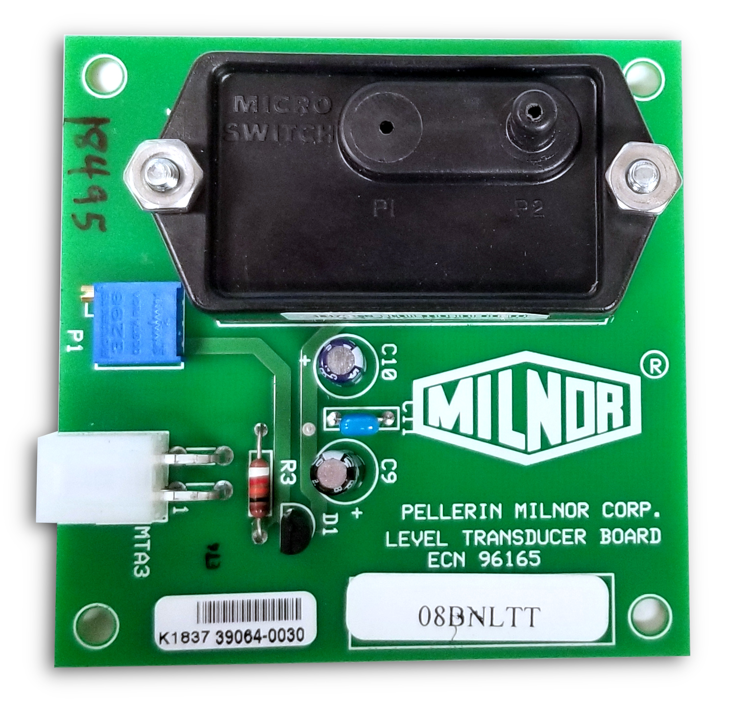
08BNLTT
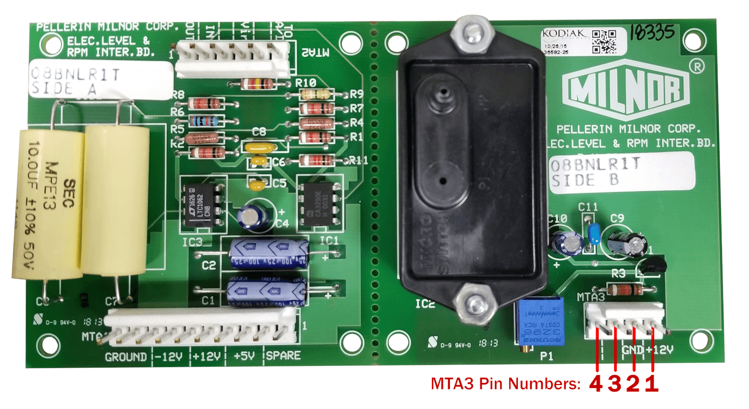
08BNRIT: Includes interpret board
Relevant images are shown below
I. TEST FOR FAULTY TRANSDUCER.
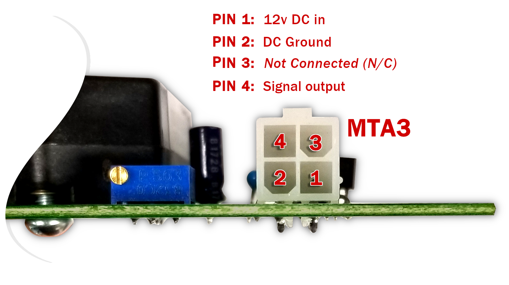
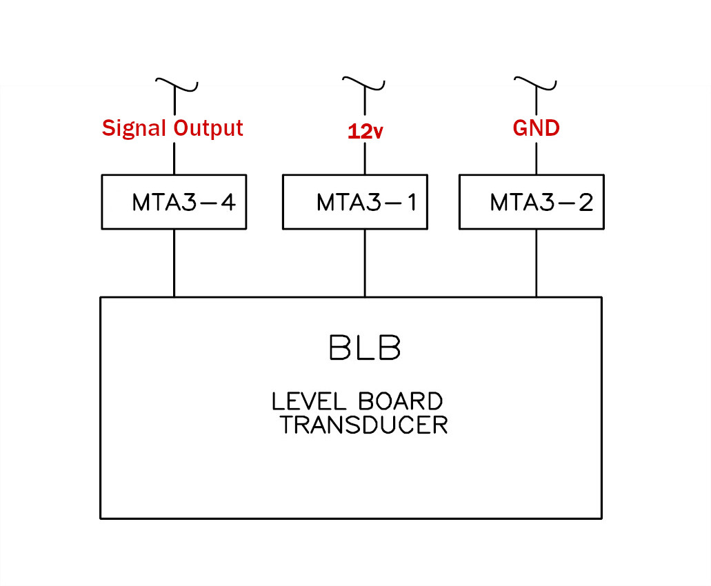
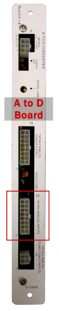
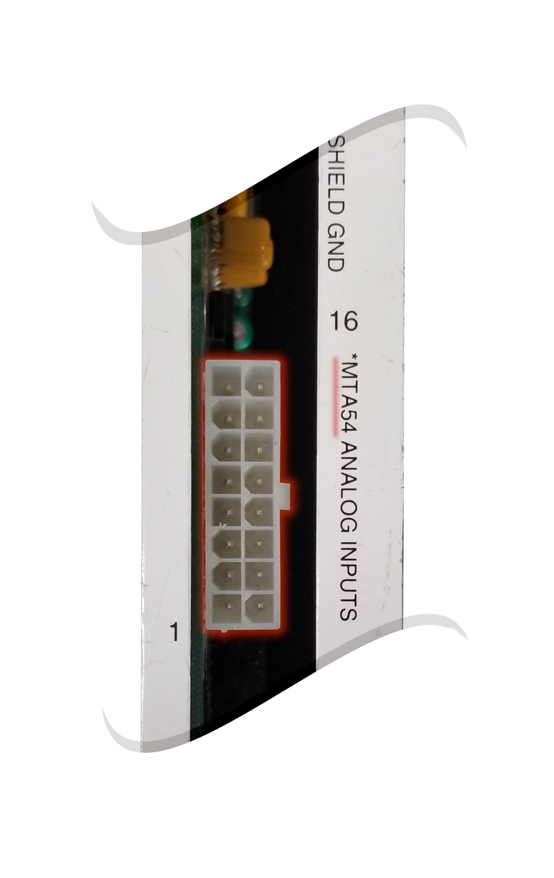
1. Pin 4 on the MTA3 plug is the output signal from the pressure transducer plug. There are two different level transducer boards; 08BNLTT and 08BNRIT. The pinouts for MTA3 of each board are shown below. The output signal from the level transducer board goes to the *MTA54 plug on the A to D board in the card cage of your machine (pictured below). Unplug *MTA54 from the A to D board to disconnect the output. If your machine is using the 08BNLRIT transducer board then the output will be routed through an interpret board. You will still disconnect the output by unplugging *MTA54 at the A to D board.
 2.
2. Check for 12v DC across pins 1 & 2 on MTA3 of the level transducer board. Then measure the output signal across pins 2 & 4. 1 volt should be measured when the output unhooked from the A to D board. If you do not measure 1 volt on the output then the level transducer board needs to be replaced.
II. TEST FOR AIR LEAK.
Note: The machine will overflow if you don't turn off the water in step 2!
-
Measure the voltages on the transducer. There should be +12VDC on the input pin and approx. 1 VDC on the output pin with no water in the basket. With the output wire still disconnected, program a bath soak with high level.
-
While the machine is filling, measure the voltage on the output pin of the transducer. It should rise from 1.0VDC to some voltage less then 6.0VDC. It rises approximately 1VDC per 11" of water. Once high level is reached, turn off the water at the wall.
-
With the machine at high level, monitor the transducer output voltage. It should remain stable.
III. TEST FOR EMI NOISE FROM INVERTER.
-
Re-connect the wire to the output pin on the transducer.
-
Program a 2-way wash cycle with high level.
-
While the machine is filling in the 2-way bath, press button 9 on the keypad to monitor the middle numeric value on the display which indicates the centimeter level.
-
If the centimeter level on the display goes to zero while the basket is turning and then to the correct level during dwell, then there is an EMI problem. To correct this problem, make sure the shield on the 4-conductor cable (from the 6" X 6" transducer box to the low voltage box) is grounded properly. The shield should be grounded to the copper bus bar in the low voltage control box and disconnected in the 6" X 6" transducer box.
