Wiring (Serial Communications)
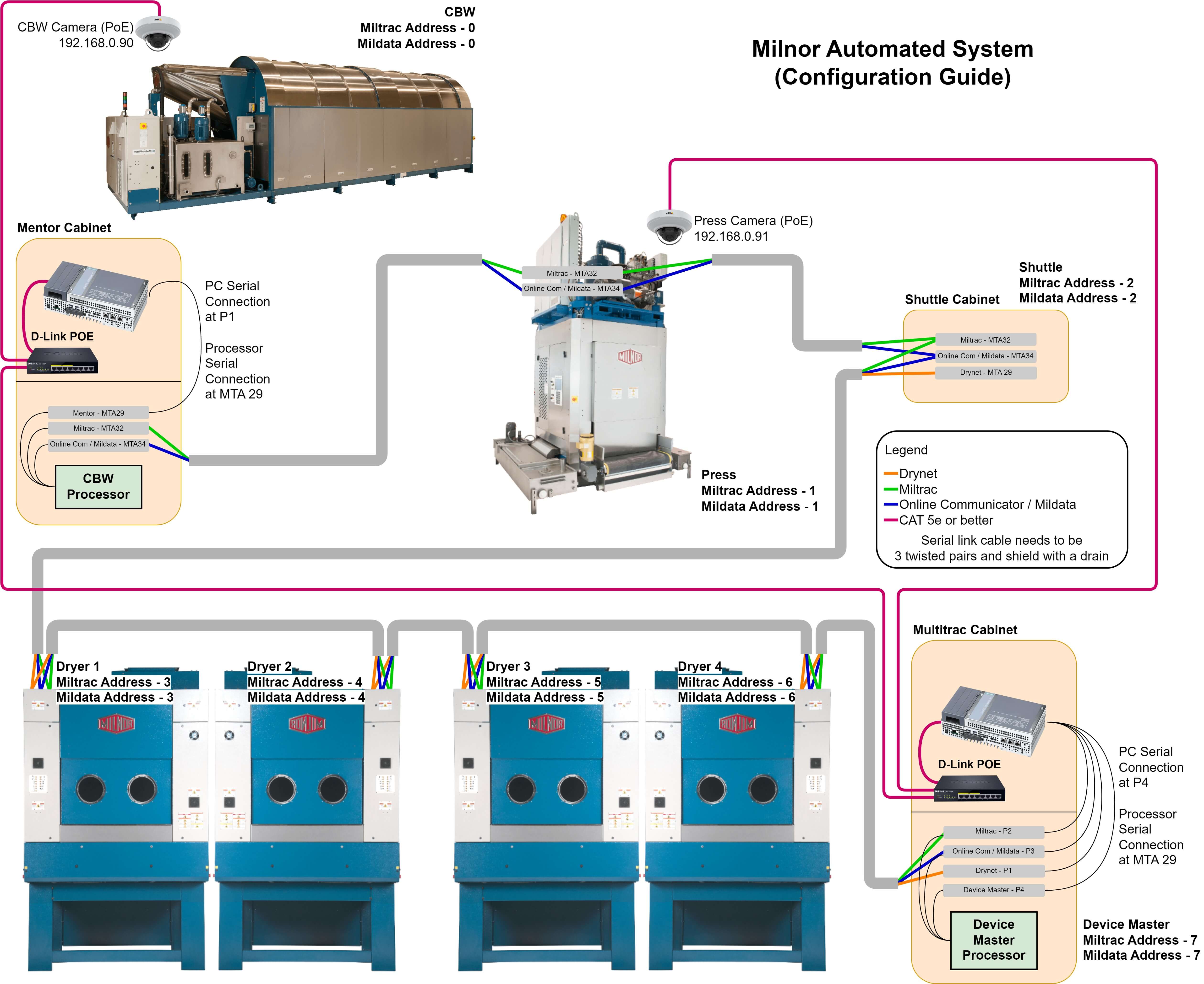
Serial communication is key for the automated systems to function properly. Milnor devices use RS-485 serial communications, and the cable need is a 3 pair, twisted, shielded serial cable. This example's color guide is as follows.
Green Twisted Pair for
MiltracBlue Twisted Pair for
Mildata/Online CommunicatorOrange Twisted Pair for
Drynet
The Multitrac PC should always be at the end of the serial link. This will allow us to have the most stable communication link between machines.
The connection points may vary based on the year your machine was manufactured. To find the termination locations, open the schematic for the machine to the
Board Wiring Page. Here you can see the termination points for the communications cable. Remember, every machine uses
Miltrac and
Mildata, but only the shuttles, COBUC, CODUD and dryers use
Drynet.
Grounding Serial Communications
Voltage potential will destroy a serial communication link. To prevent this, wiring is key.
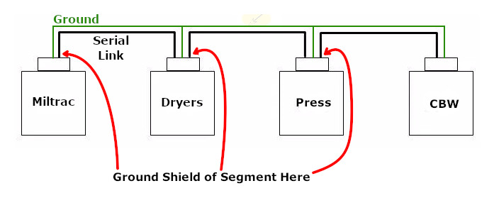
We typically will use a daisy-chained serial link. This style is best for preventing interference from electrically induced noise.
The ground is connected to each component.
The serial cable is separated into segments. This diagram has three segments.
The shield on each segment should only be grounded on one end. See the diagram below.