The Linde hydraulic pump, part number
27E55057, allows up to 6000 psi pressure without a separate "booster" pump circuit.
There are some differences in the previously used Kawasaki VDPP and the Linde. The Linde does not have an onboard pressure compensator. It uses the proportional valve and the system relief to prevent over-pressurizing the system. They use the Load Sense port as the Horsepower compensator. The pump come preset at 30 HP but can be adjusted upward for larger motors.
If the pump loses control of pressure compensation, due to a proportional valve failure (failing closed), the pump will pressurize to 6000 psi. Also know that blocking the proportional valve supply hose will cause 6000 psi outlet pressure. Rod failure is possible with these pressures! The safety system depends on the proper setting of the system relief.
The system relief will dump any pressure over the max desired for the press model. The system relief valve dumps main flow from the pump to tank as it always has. The system relief is provided with a key lock to prevent tampering by unskilled persons. Replacement system relief valves must be adjusted properly for safety and then locked.
A horsepower compensator is onboard which can be adjusted to the "no flow" max pressure. See below.
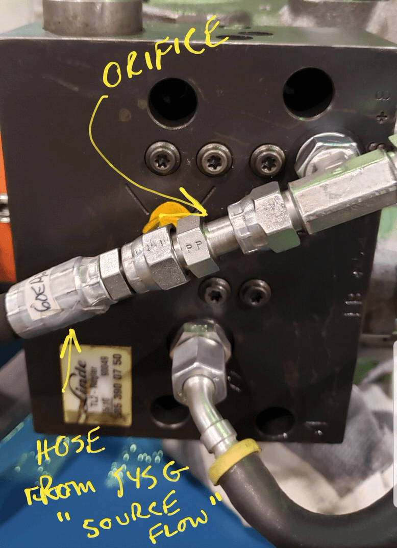
The pump does not produce flow at the control port for the proportional valve. So, the system pressure port (found at the gauge port marked SYSG, is used to supply pressure to the compensator port through a hose. This flow is through an orifice and the line is relieved back to tank through the proportional valve. If for any reason the orifice is removed the proportional valve cannot bleed enough fluid (due to its size) and the pump will run at higher than desired idle pressures. We have seen it not able to run below 2000 psi without the orifice. Do not remove the orifice inline with the supply hose. If for any reason the orifice is plugged or obstructed (it is .8mm) the pump will not pressurize.
The load sense input is fed from the system pressure, so, if you have a leak to tank from the system and cannot achieve pressure, the pump will not try to pump at a higher rate. In the case of a 30 HP motor (480 v example) Idle amps will be about 14 amps and max pressure will be at 40 amps. But a leak at low pressure...like a bypass valve stuck open...will only cause an amp draw at about 20 amps. This is because the pump head pressure cannot actuate the load sense plunger in the pump to drive the HP request higher. This is unlike a Kawaski pump and may confuse troubleshooting practices.
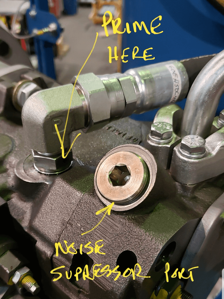
Priming the Pump
When starting a new pump, see the picture for the priming oil inlet. Do not remove the noise suppressor port plug for priming.
Proportional Valve Fittings
The hose below from the source feed is connected to the SYSG port in the manifold. The orifice function is described above. The hose to the right of the T fitting in the pump leads to the proportional valve inlet in the manifold.
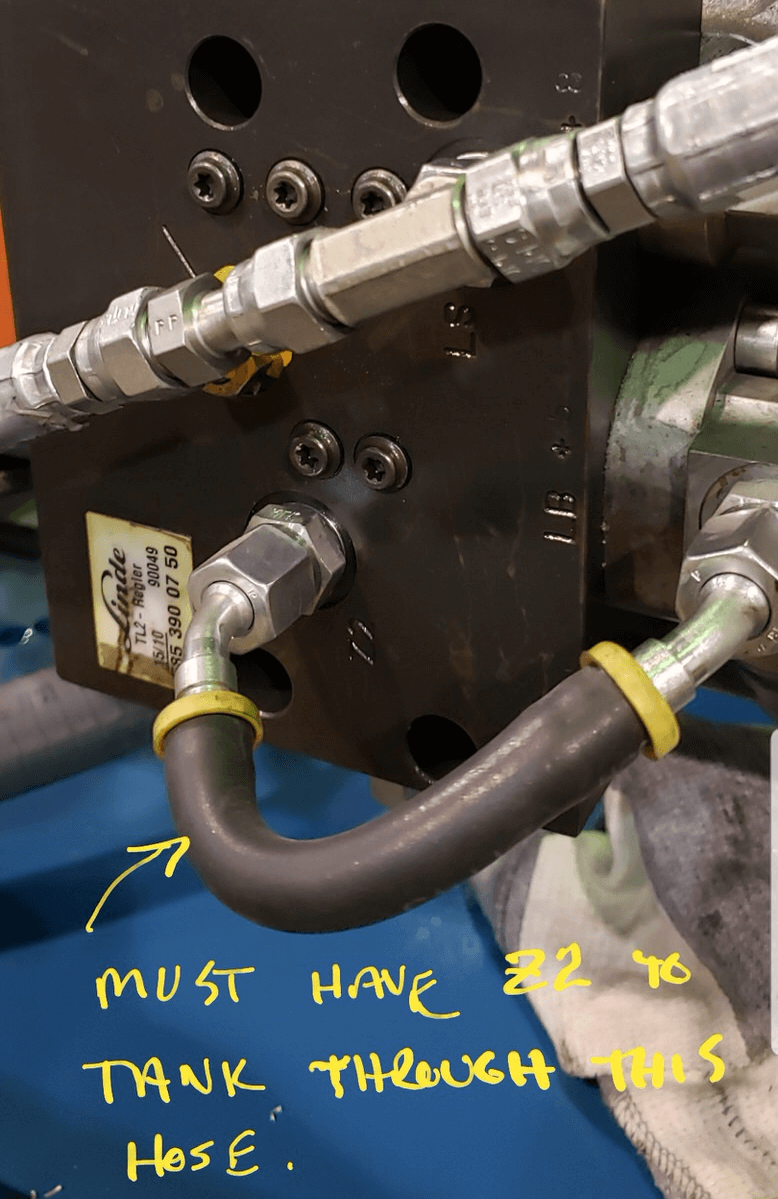
Hose from LB to Z2
This hose is needed for the pump to operate properly. Port Z2 must go to tank.
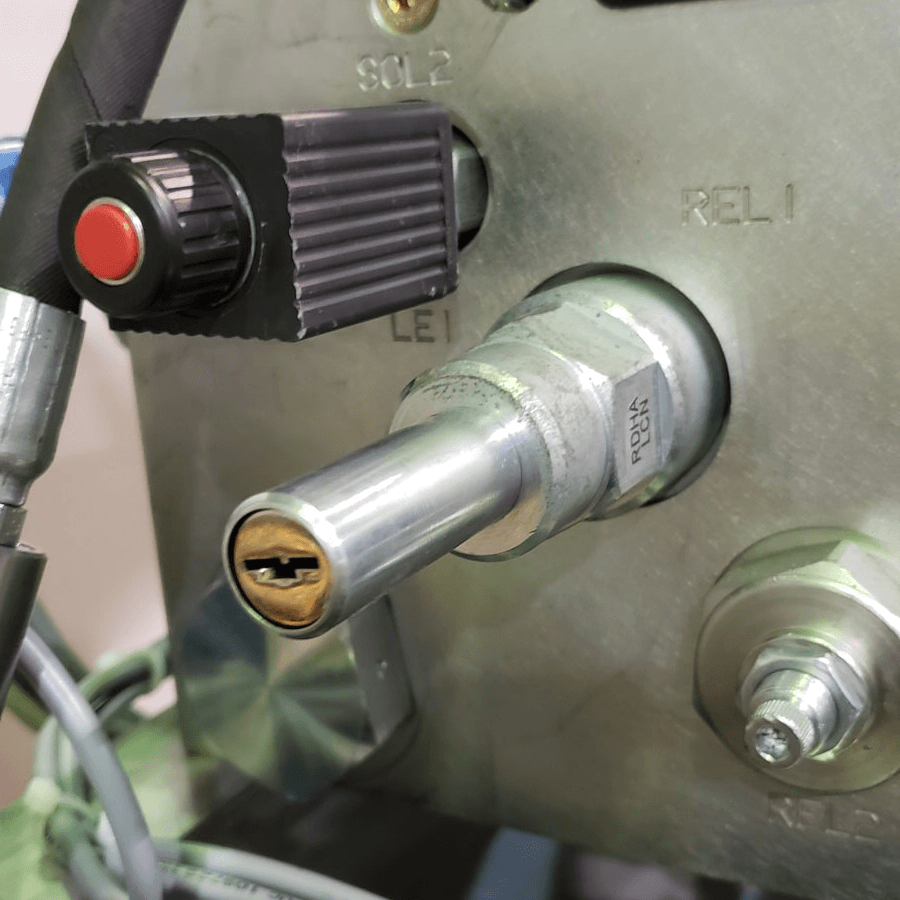
Key Lock on System Regulator
This lock is provided to prevent tampering with the system relief. The pump can produce more pressure than the mechanical system can tolerate. It is possible to over-pressurize the cylinder and fail the tension rods. After the system relief is set by skilled personnel, it is locked to prevent incidental adjustment. REL1 is the system relief.
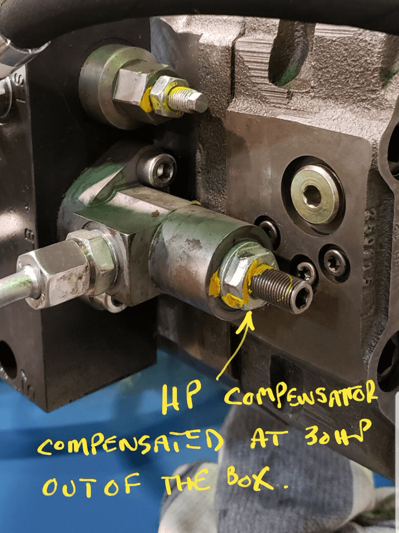
HP Limit / Compensator
The HP limit is adjusted to limit motor HP consumed. The pump comes from Linde compensated at 30 HP. Larger motors require a pump adjustment for maximum performance. Small angular adjustments create large changes in HP required. we suggest running at a maximum of 90% of the FLA of the motor.
Unlike the Kawasaki pump this Linde pump has only one HP adjustment. This adjustment is for high pressure HP compensation. This may lead to some confusion when you are pumping to a low pressure leak. The pump HP demand is limited when pumping at low pressure. As an example, we see full load amps at 40 at high pressure, idle amps at 16 and an amp draw in the low 20's when pumping to a low pressure leak. So, when troubleshooting, if you see amps in the 20's and you cannot achieve pressure, look for a leak to tank...not a control problem from the proportional system.
Schematic and physical pump port sheet
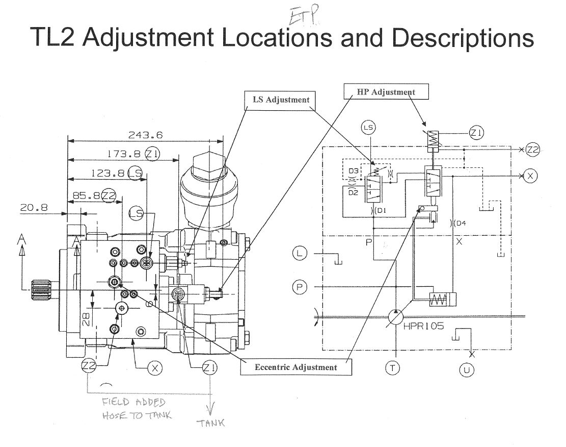
The following notes are from the Linde pump service manual as a guide to understanding the function. No LS or eccentric adjustment is needed to the pump in the MILNOR application. We only adjust the HP adjustment depending on motor size.
LS Adjustment
Adjusts like all HPR-02 LS adjustments. Turn in to increase LS Delta P, out to decrease.
HP Adjustment
Turn adjustment screw in to increase mechanical HP setting, out to decrease.
The HP setting can also be artificially changed with pilot pressure. Adding pilot pressure to port Z1 increases the HP setting. The amount of increase is dependent on the magnitude of the applied pilot pressure and the area ratio of the TL2 control parts selected per the application’s specifications. If port Z1 is not used, it MUST be drained to tank. This is done with an external connection from port Z1 to some tank source via a hose or tube.
Port Z2 is used to hydraulically lower the HP setting with pilot pressure. The amount of HP decrease is dependent on the magnitude of the applied pilot pressure and the area ratio of the TL2 control parts selected per the application’s specifications. If port Z2 is not used, it MUST also be drained to tank. But unlike draining port Z1 which must be physically plumbed to a tank source, port Z2 can be set up to internally drain to the pump case when not used. In this set up, the internal Z2 drain passage is open to case and a steel plug is installed in the external Z2 port. This is the standard factory set up of port Z2. If port Z2 is to be used, the internal drain passage is plugged and the external Z2 port is opened for the pilot supply line connection.
If neither Z1 or Z2 port is used, Z2 should be set up to drain internally as described above. Then port Z1 could be plumbed to external port Z2, and both ports would drain internally via Z2.
Eccentric Adjustment
This adjustment is done in test after examining the shape of the constant HP curve. At pressure above ~3000 PSI, the HP curve may have a tendency to diverge away for the constant HP setting. This eccentric adjustment is used to bring the end of the HP curve back on the track of constant HP.
Adjustment to this Eccentric should not be attempted unless the shape of the HP curve can be acquired in the process and examined to determine / verify the adjustment’s related impact and benefit.
Pump Leaks
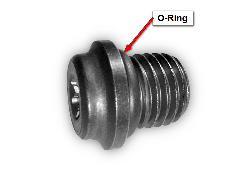
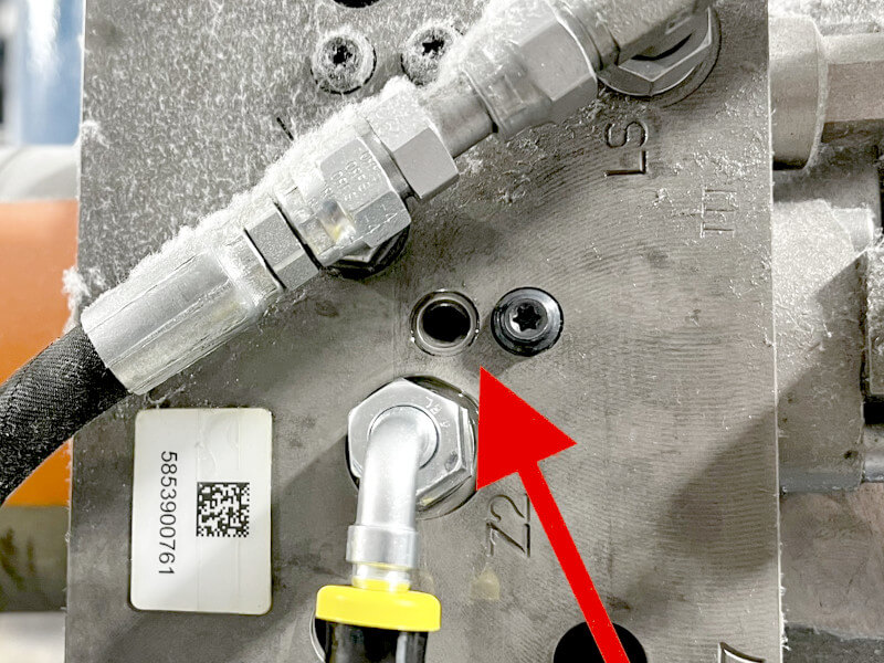
The most common leak seen on the Linde pump is typically a small M8 plug with an o-ring. This plug has a torque specification of 6 lbs-ft. A picture of a pump with a leaking plug can be seen below along with a picture of the plug in general.
| Part number 27E55057M8 - | M8 PLUG FOR LINDE PUMP |
Note: Do not exceed the torque specification! This can damage the o-ring and cause further leaks.