Why do I need to set addresses on my boards?
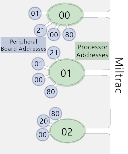
In the same way your home has a unique address, each peripheral board will have unique addresses to the processor board, and each processor will have unique addresses to Miltrac or another program.
Note: Programs like Miltrac do not communicate with peripheral boards. Peripheral boards only communicate with the processor.
The diagram to the right illustrates the addressing similar to a street address. Miltrac connects to all of the uniquely addressed "streets" or processors. Then, each processor connects to its own uniquely addressed "houses" or peripherals.
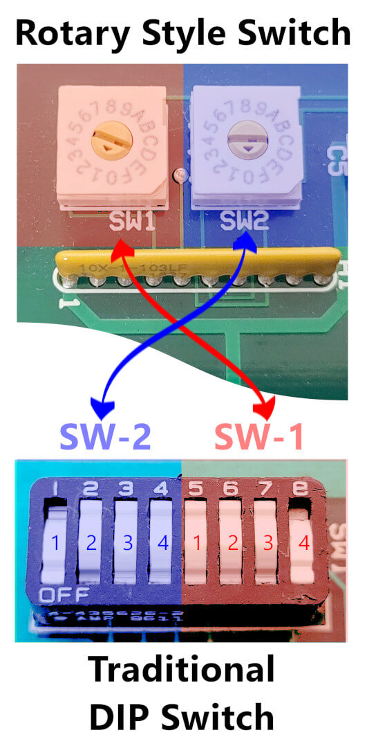
The address is set by either a bank of traditional DIP switches or two rotary style switches pictured below.
How do I set addresses?
Addresses are set using the either the traditional DIP switch or a rotary style switch. A1, 21, and 0F are all possible examples of an address.
For A1:
A is the most significant digit and is set by
SW-2 in the diagram below
1 is the least significant digit and is set by
SW-1 in the diagram below
Traditional DIP switch is separated into two sections. SW-2 is set by positions 1-4 and SW-1 is set by positions 5-8. Rotary switches are labeled appropriately on the board for SW-2 and SW-1. Rotate the switches to correct values and the address is set.
Switch Set 1-2-3-4 (Binary)
1=ON, 0=OFF | Hexadecimal | Decimal |
|---|
| 0-0-0-0 | 0 | 0 |
| 1-0-0-0 | 1 | 1 |
| 0-1-0-0 | 2 | 2 |
| 1-1-0-0 | 3 | 3 |
| 0-0-1-0 | 4 | 4 |
| 1-0-1-0 | 5 | 5 |
| 0-1-1-0 | 6 | 6 |
| 1-1-1-0 | 7 | 7 |
| 0-0-0-1 | 8 | 8 |
| 1-0-0-1 | 9 | 9 |
| 0-1-0-1 | A | 10 |
| 1-1-0-1 | B | 11 |
| 0-0-1-1 | C | 12 |
| 1-0-1-1 | D | 13 |
| 0-1-1-1 | E | 14 |
| 1-1-1-1 | F | 15 |
Let's look at address A1 as an example for DIP switches
| Switch Number in Set | 1 | 2 | 3 | 4 | 5 | 6 | 7 | 8 |
|---|
| Example Setting (1=ON, 0=OFF) | 0 | 1 | 0 | 1 | 1 | 0 | 0 | 0 |
|---|
Using the table above,
A is represented by its four switches being
OFF - ON - OFF - ON. Set
positions 1-4 in this order.
1 is represented by
ON - OFF - OFF - OFF. Set positions
5-8 in this order.


