First, confirm that the sensors are clean and free of any algae growth that would cause a false sensing of the scoop blocked. Specifically, the wires under the chute should be clean and free of any algae growth.
New stainless chute sensor wires are part number ECA9B083S. This includes twelve - 6" wires and six - 9" wires and eighteen each of small and large Viton washers.
If the entire chute sensor assembly needs to be replaced, there are two assemblies to choose from.
A80CS001 / CHUTE SENSOR ASSY FOR A 16 POSITION CHUTE SENSOR ASSEMBLY (pictured below)
A80CS002 / CHUTE SENSOR ASSY-MP1A03 FOR AN 18 POSITION CHUTE SENSOR ASSEMBLY
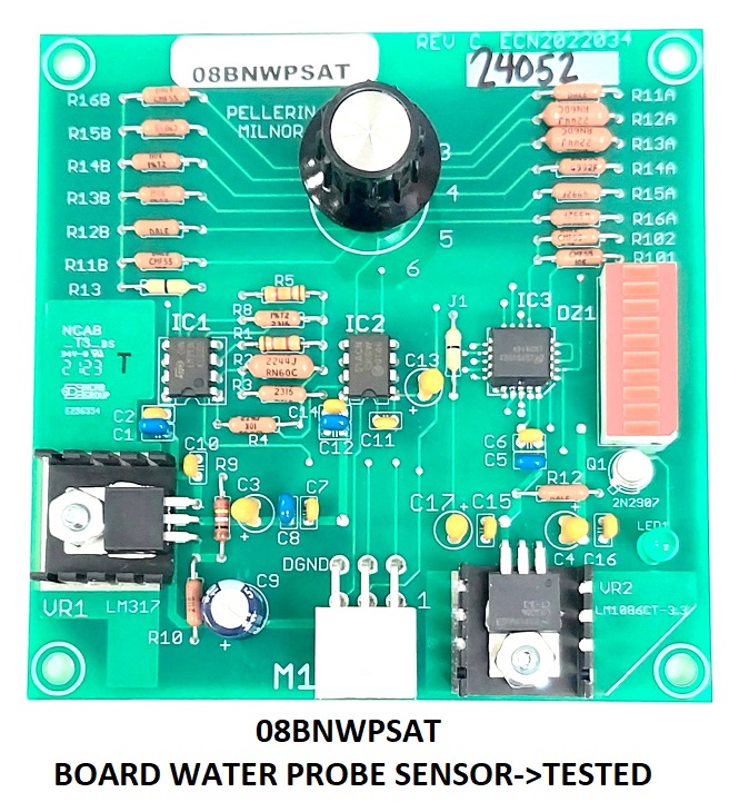
Water Sensing Board
Sensitivity Knob
The sensitivity knob can be set from 1-6. 1 is the least sensitive and 6 is the most sensitive.
Red LED Array
This LED array shows the current resistance between the load chute probes. During normal operation, the LED array is fully lit when the load chute probes are clear of linen. When wet linen passes the load chute probes, resistance drops between the probes and the LED array turns off either partially or fully, depending on the resistance. This LED array is not affected by the sensitivity setting. Think of this like
Green Indicator LED
The green indicator LED turns ON once we cross the resistance threshold set by the sensitivity knob.
Setting the Water Sensing Board
If you are replacing a water sensing board, set the sensitivity the same as the previous board.
If you are setting the board for the first time, follow these steps.
- Set the sensitivity knob to 4.
- Watch a load transfer into the press.
- Watch that the green LED indicator turns on then off once the load clears.
- If it does not turn on raise the sensitivity knob by one.
- Take a wet piece of linen and bridge two adjacent load chute probes.
- Verify the green LED indicator is lit with the two probes blocked.
- Test.
- If you start having nuisance trips from water splashing out of the CBW, lower the sensitivity knob by one.
The sensing board is part number 08BNWPSAT.
In addition to algae, we have found crystalized acid formations on the sensor wires. This wet crystalline structure helps conduct the sensing voltage and can also cause false reading of conductivity. Simply put, the wires must be free and clear of any contamination. Clean wires and insulators are the key to proper performance. Do not allow the wires to touch each other or the stainless chute. This touch point could cause false trips.
The Load Chute Blocked (load scoop) fault occurs when the sensors on the load chute detect the presence of material on the chute that the descending diaphragm could hit. This is very important because after we pressurize the ram, almost anything can be pushed into the can and cause irreversible damage.
In a few cases the timing of the transfer and related programming may allow a false trip. Water that enters or remains on the load chute while the diaphragm moves down can cause an unnecessary fault. You must adjust two interrelated configure decisions to avoid this.
The Decisions are:
Loading Time
in the press controller-Free water that comes out with the goods can remain on the press load chute for a few seconds. A value of 4 seconds is usually sufficient to allow this residual water to flow off of the load chute before the sensors are armed.
Pause at Top Dead Center in the Mentor Control
Water can splash out of the tunnel after the cylinders start to turn following transfer and cause a fault in the press. The load chute sensors remain armed until the press diaphragm enters the can on its descent. Specifically, the sensors are disarmed when the PXSM proximity switch (Ram inside Can) is no longer made (which tells the controller that the diaphragm is inside the can). The time it takes for this to occur can vary with the press model and with conditions such as whether the press is fully broken in. The value you enter here must be long enough to accommodate the press Loading Time plus the time for the diaphragm to descend into the can. As a starting point, assume a 3 second descent time. If the press Loading Time is 4 seconds, enter 70 tenths (4 + 3 = 7 seconds) here.
Observe the press load chute during and after transfer to make sure these timer values provide the necessary protection against unnecessary faults. Adjust them accordingly.

