The Big Idea
Milnor employs an orange elastomeric coupling in both CBW drive trains and some hydraulic pump systems. These couplings are commonly referred to as pumpkins, due to shape and color. Elastomeric couplings are a flexible coupling that helps transmit torque, dampen vibration, and provide for potential misalignment. The ‘pumpkin’ couplings are designed to wear out before any metal components. This not only saves time and money on maintenance but also means that the couplings do not require any form of lubrication.
The coupling (pumpkin) can tolerate some angular misalignment, but the 2 shafts MUST be aligned horizontally and vertically at the shaft ends. Like, the shafts must be pointed directly at each other, not high or low or left or right.
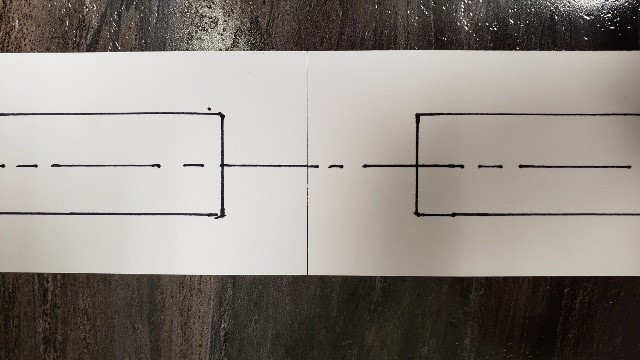
Perfect Shaft Alignment (which is highly desirable)
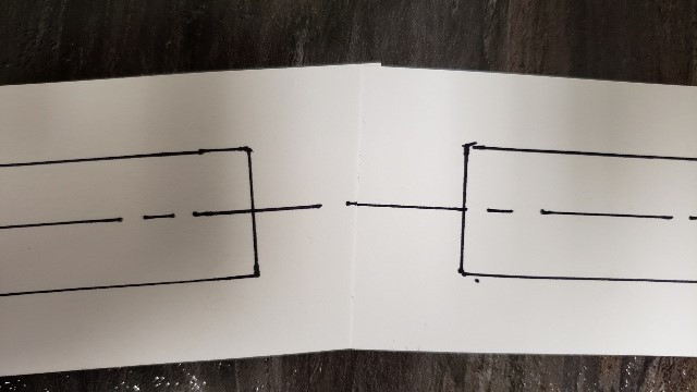
Tolerable Shaft Misalignment (exaggerated)
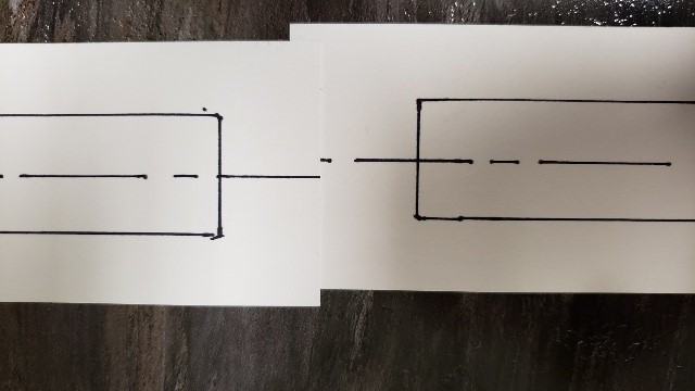
Poor Shaft Alignment (you will damage the coupling)
This picture shows poor shaft alignment that
will cause coupling failure; an 1/8" misalignment will cause regular coupling failures every few months. 1/4" misalignment will cause a failure in a week). If this condition exists on your welded frame CBW (models 76039 and 76028) then the frame joints between sections should be unbolted and realigned to ensure coupling alignment. The frame can be offset and use smaller bolts or reamed holes.
DO NOT SHIM THE GEAR BOXES. Shimming gear boxes may make the gear box leak oil which will result in failure of the gear box.
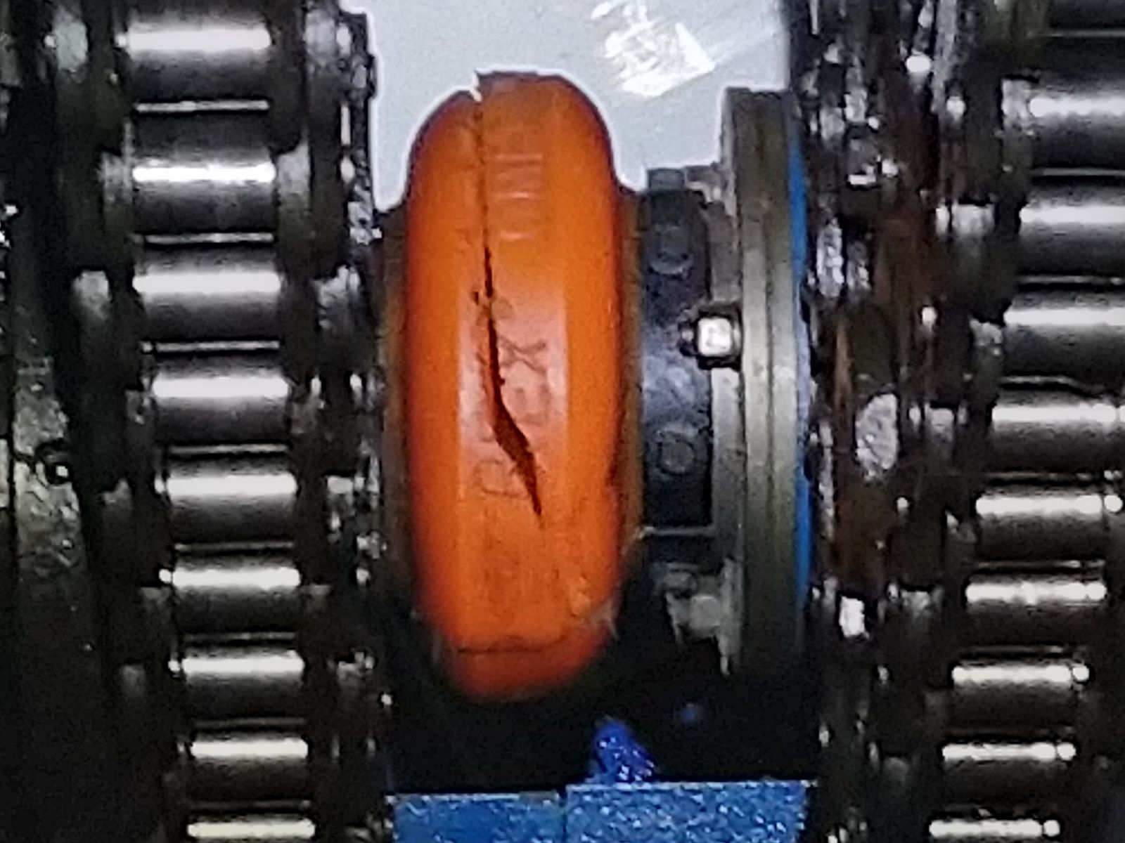
Here is an example of a misaligned coupling that failed in 3 weeks after installation. You can see that the vertical misalignment was over 1/8"
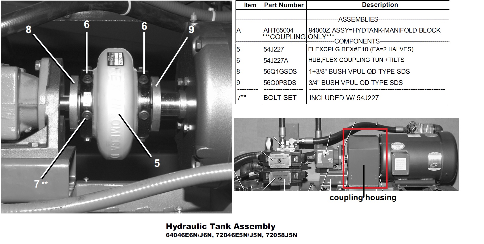
***NOTE ON BUSHINGS CONNECTING COUPLING TO DRIVE SHAFTS***
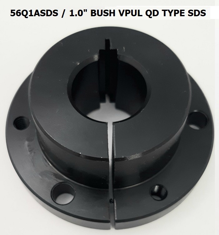
Bushing parts listed in diagrams are standard, however, due to customization the coupling part numbers may vary. See bottom of page for a list of the SDS bushing part numbers and their corresponding measurements or click
here
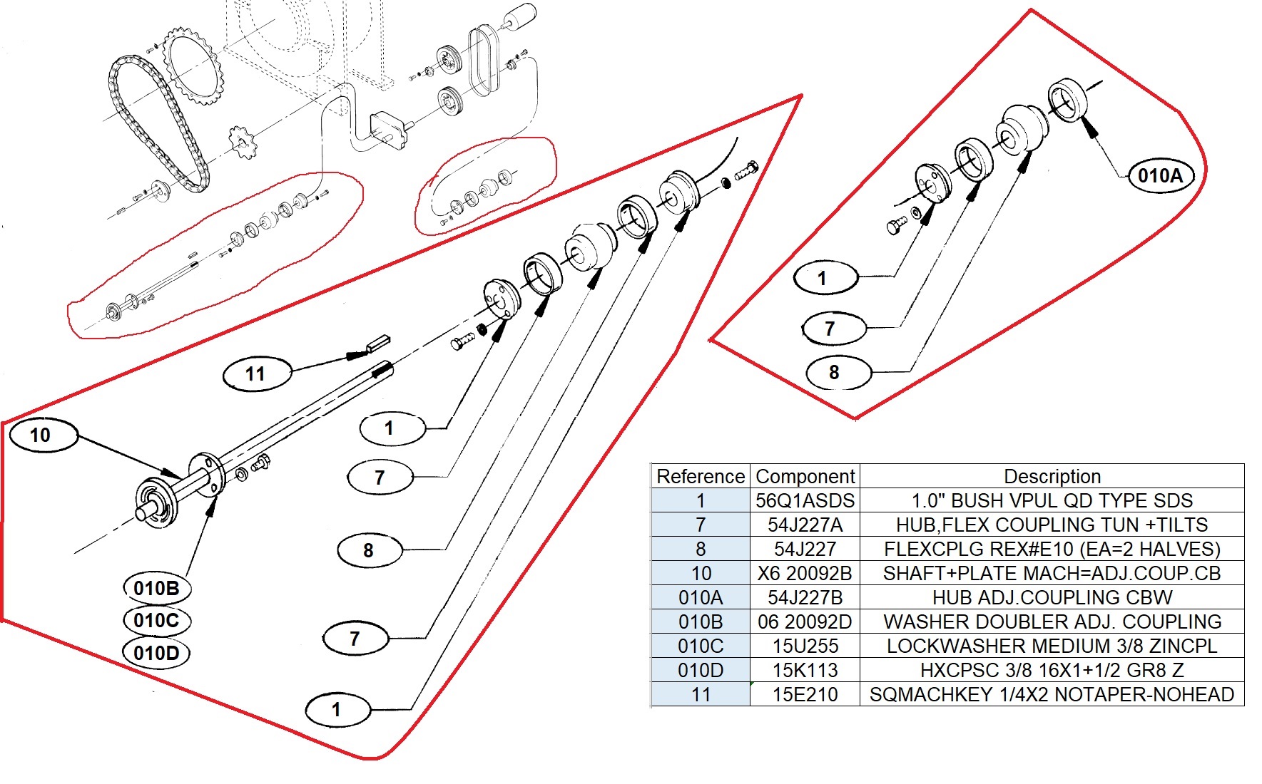
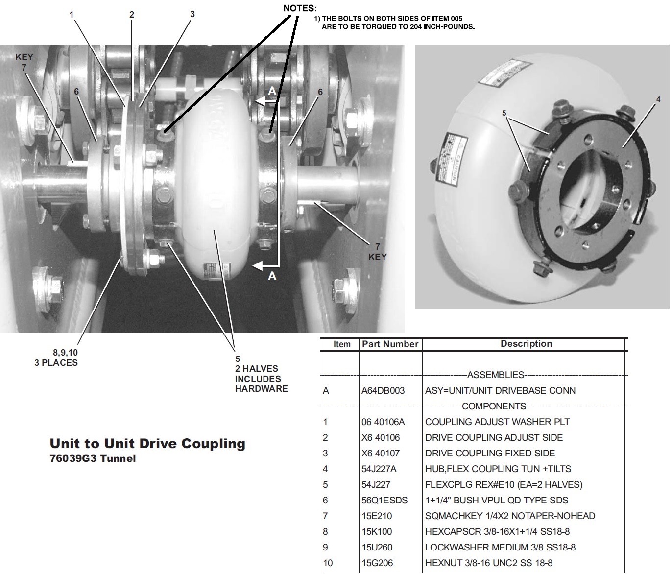
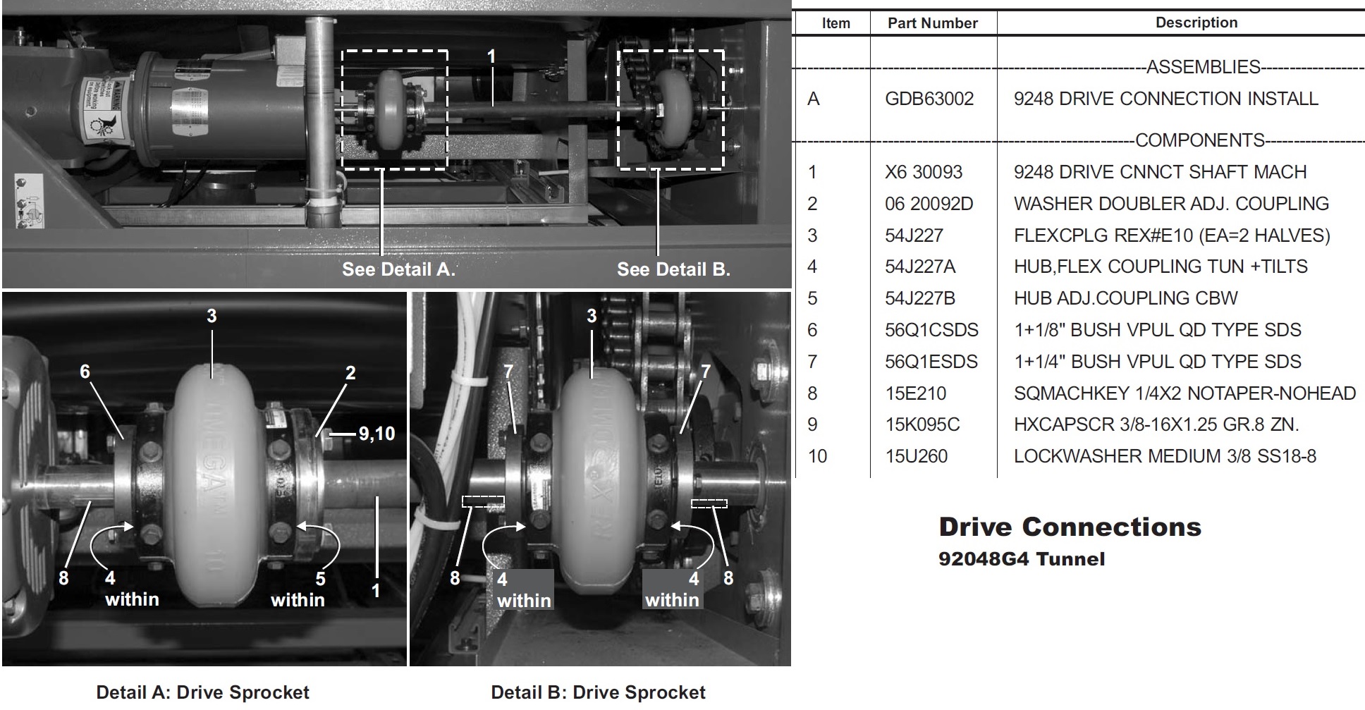
The coupling part number is 54J227 (pictured below).
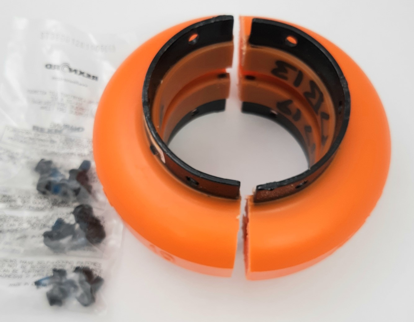
There are three hubs that bolt into the coupling.
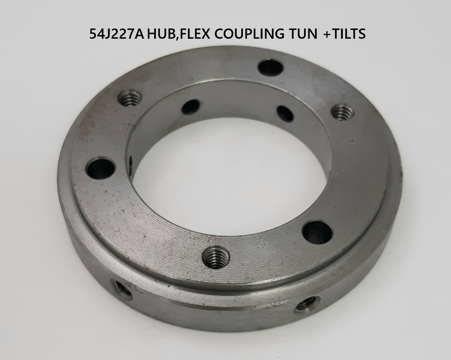
1) 54J227A / HUB,FLEX COUPLING TUN +TILTS - Bushings bolt into this hub. Key connects bushing to drive shaft.
 +
+ 
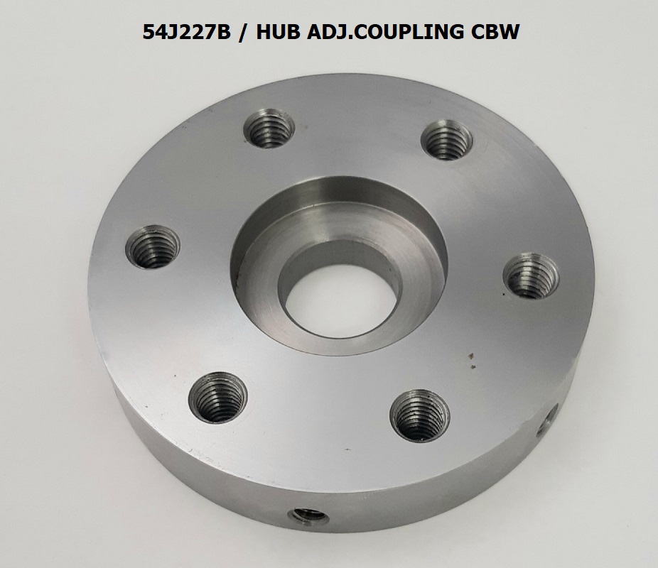
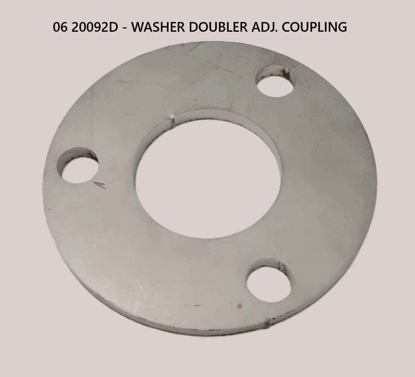
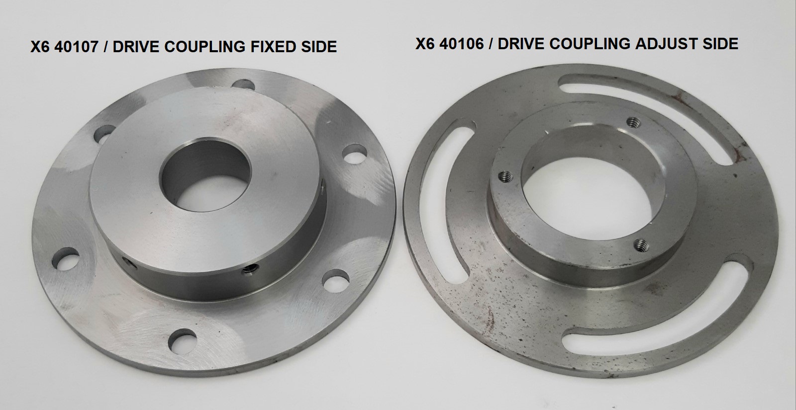
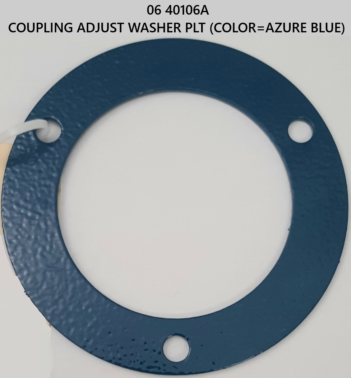
2) 54J227B / HUB ADJ.COUPLING CBW – joins to a shaft with plate shaft combo and washer
 +
+  +
+ 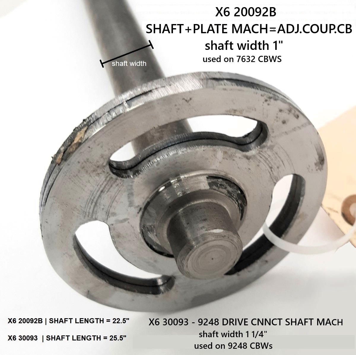
X6 40107 / DRIVE COUPLING FIXED SIDE & X6 40106 / DRIVE COUPLING ADJUST SIDE
– attaches to washer and bushing combo.
 +
+  +
+ 
PARTS DIAGRAMS
CBW G1 (76032 MODELS)
DRIVE ASSEMBLIES D62 00360, D62 00350, D62 00360L, D62 00350L (L=last module=does not contain part # S6 20092B)
CBW G2 & G3 (MODELS 76022, 76028, 76039)
PART ASSEMBLY A64DB003
G4 (MODEL 92048)
PART ASSEMBLY GDB63002
HYDRAULIC TANK COUPLING ASSEMBLY (MODELS 64046E6N/J6N, 72046E5N/J5N, 72058J5N)
COMPLETE HYDRAULIC ASSEMBLY AHT65004 - ONLY COUPLING PARTS LISTED HERE
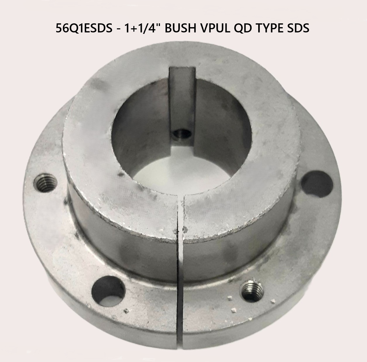
COUPLING PART NUMBER SIZE CHART
| PART NUMBER | DESCRIPTION |
|---|
| 56Q0MSDS | 5/8" BUSH VPUL QD TYPE SDS |
| 56Q0PSDS | 3/4" BUSH VPUL QD TYPE SDS |
| 56Q0RSDS | 7/8" BUSH VPUL QD TYPE SDS |
| 56Q1ASDS | 1.0" BUSH VPUL QD TYPE SDS |
| 56Q1CSDS | 1+1/8" BUSH VPUL QD TYPE SDS |
| 56Q1ESDS | 1+1/4" BUSH VPUL QD TYPE SDS |
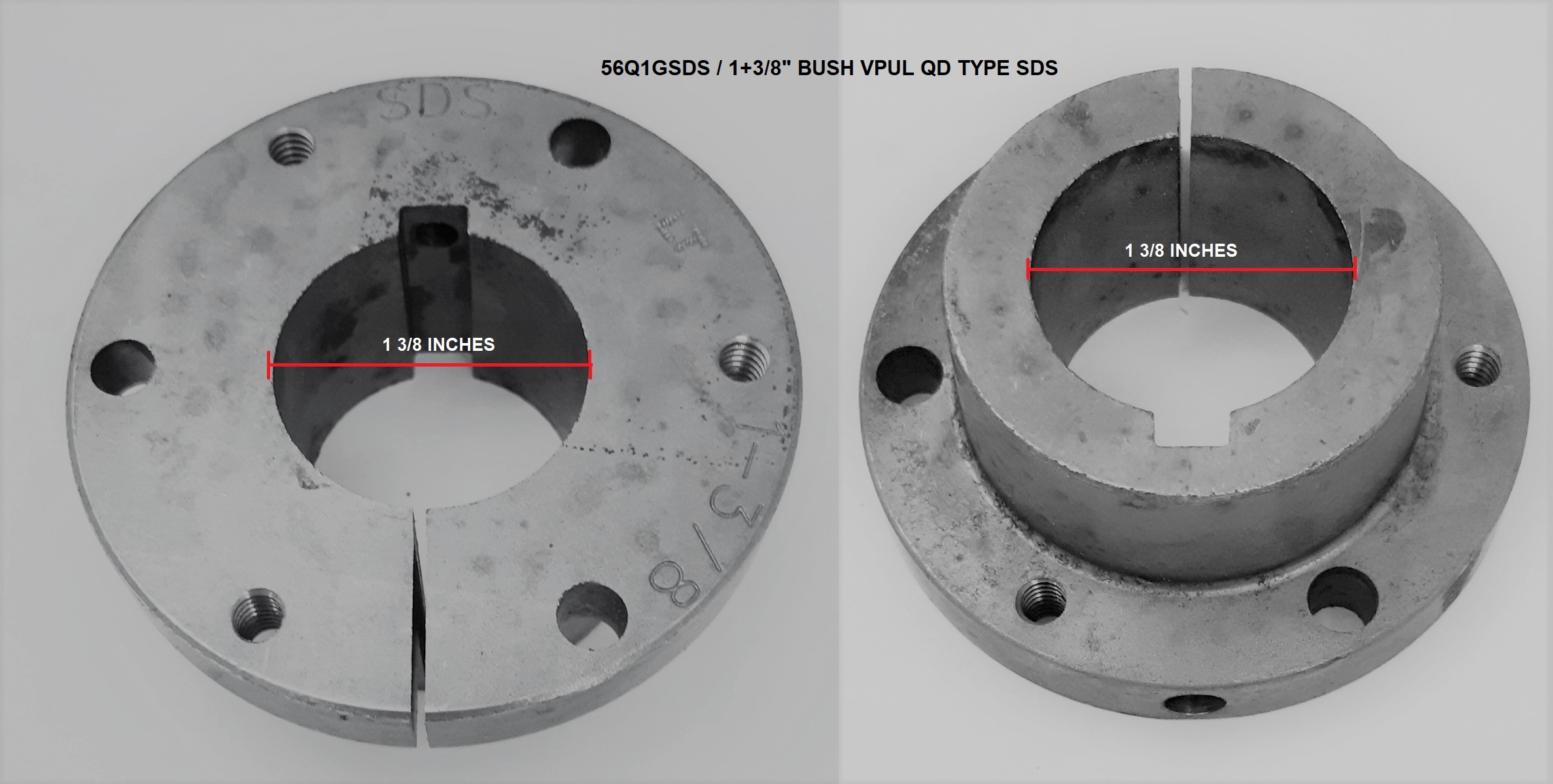
| 56Q1GSDS | 1+3/8" BUSH VPUL QD TYPE SDS |
| 56Q1KSDS | 1+1/2" BUSH VPUL QD TYPE SDS |
| 56Q1MSDS | 1+5/8" BUSH VPUL QD TYPE SDS |
return to top of page
