INSTRUCTIONS TO CHANGE A SHUTTLE HOIST FROM EARLY DEMAG (not inverter driven) TO THE NEWER STYLE HOIST (inverter driven) WIRING
The following parts will be needed to perform this conversion
1 Demag DC — Pro hoist
1 27KH050KIT
1 Length of 4 conductor festoon cable
Retro fitting the hoist will require mechanical and electrical changes to the shuttle. There will be changes made to the existing control circuitry that will require an additional 4 conductor festoon cable be added to the existing festoon cable assembly. Please read and understand these instructions thoroughly before beginning the change.
MECHANICAL
The upper cross member of the shuttle will not work with the new hoist. Therefore, it must be changed to the new cross member supplied with the kit.
ELECTRICAL
The existing Hoist uses a reversing contactor (CSXSU and CSXSD) to raise and lower the hoist by reversing the polarity of the three-phase power to the hoist motor. The reversing contactor is located in the shuttle control box at the end of the rail. The new hoist employs an inverter driven motor. It reverses direction based on inputs made to the control circuitry of the new hoist. A constant three phase power is applied to the new hoist.
The existing reversing contactor (CSXSU and CSXSD), that is now used to raise and lower the hoist by changing the polarity of the three-phase, will no longer be used. One half of the reversing contactor will be used to apply power to the inverter. By doing this the existing three phase wiring from the reversing contactor to the hoist can be reused and denoted as CSH. CSH will be wired per schematic W6SH5SHS, version 2007223B. The contactor should pull in when the 3-wire energizes on the shuttle. CSH will put three phase power to the inverter.
To make the inputs to the hoist circuitry that raise and lower the hoist, two adjustable time delay relays (
09CAO1SM74) must be mounted in the shuttle control box. These relays are
CDUP and
CDDN. The relay coils will use the same signals that were used for the coils of
CSXSU and
CSXSD. Refer to schematic W6SH5SMC, version 2007064B. Please refer to the instructions on the relays and set them for "TIME DELAY ON" with a range of 0-10 seconds. The relays should be set to operate at 0.3 seconds. This setting should have the relays energize 0.3 seconds after voltage is applied. Schematic W6SH5SHS will indicate the additional control wiring needed for the new hoist.
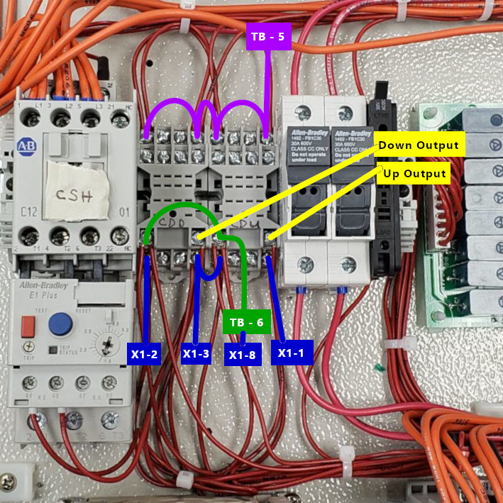
There is an overload contact in the older hoist that is no longer used. These two wires for the overload should be spliced together. This completes the overload circuit for the three-wire circuit.
An additional festoon cable will have to be added. This will allow the circuitry added in the shuttle control box to be wired to the new hoist. The festoon cable will be added from the shuttle festoon connection point to the connection box at the end of the rail. The connectors will need to be modified to accept the additional festoon cable. There should be spare wires in the cable that run from the connection box at the end of the rail down to the shuttle control box that can be used for the additional circuitry. If not, an additional cable needs to be run from the connection box down to the shuttle control box. Since the lengths will vary, additional festoon cable and control wiring is not supplied and must be ordered separately.
