The motor is only part of the story when something goes wrong electrically with your drive system. Below we have gathered descriptions of components that may be seen in the motor control system. Most of these components are located in the Inverter Cabinet on your machine.
Input (Line) Reactors
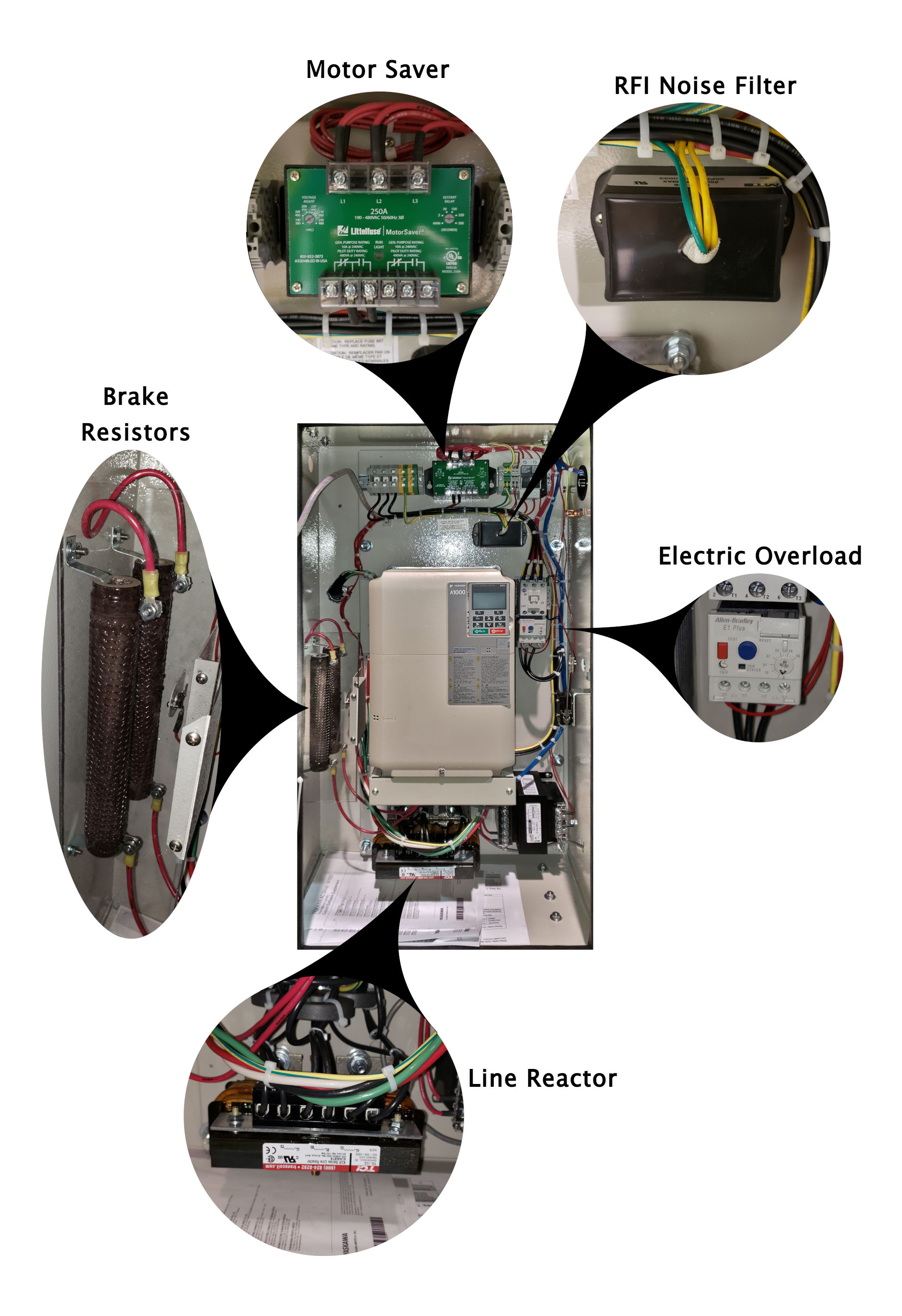
An input or line reactor helps protect a variable frequency drive (VFD) from input power line disturbances that could cause nuisance tripping or damage to the drive. An input (line) reactor also reduces the harmonics that the VFD generates back onto the line. Line reactors are sized based on the HP and voltage ratings of the drive in use.
Output (Load) Reactors
An output (load) reactor, on the other hand, is used to protect the motor if the wiring distance between the VFD and motor is very long. The drive generates a high frequency three-phase output and noise spikes are generated on the leading edge of these signals. These noise spikes get amplified due to the long cable lengths and the additional capacitance of the cable. The resulting voltage can exceed the motor’s peak voltage rating where insulation breakdown occurs. This is typically a 100ft or greater distance between the inverter and the motor. This typically will not be seen on a Milnor application unless there is a shuttle with a long run or other extenuating circumstances.
Surge Protection Devices
The surge protection devices are used to protect sensitive components on a system. Not all of these are standard equipment but can be added if noise (EMI) problems are witnessed.
The Motor Saver is used where input power is questionable, like in areas with common power outages and in applications where generator power is used as a backup to line power.