There are two systems at work on your press belt. One is the Belt Alignment System that protects the belt from being damaged when goods get wrapped around a roller and the belt drifts to one side. The second is the Taut Belt Switch System that determines when the belt is too tight and notifies the operator with an error message.
Belt Alignment Summary:
The air cylinders are used for moving the tracking roller. The "paddles", on the left and right of the belt, operate air switches which in turn move the air cylinders for belt tracking. If you actuate the right switch the belt moves left and vice versa. Neither paddle should be hit often by the belt if the primary head roller is tracked properly.
While checking the alignment system you can make the right paddle and confirm that the belt moves left. Also check that the left paddle moves the belt to the right. The air cylinder must stroke properly when the paddles are depressed. Otherwise the system is not working properly and belt damage is possible.
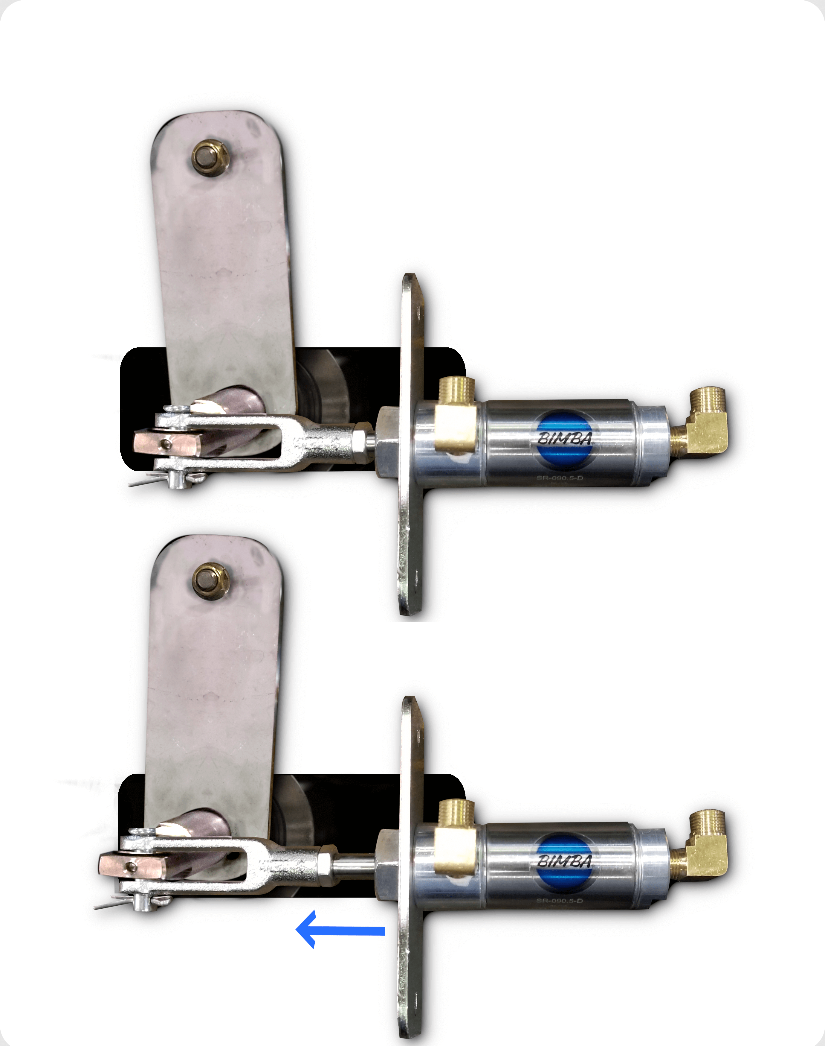
Bimba Tracking Cylinder Operation
Taut Belt Summary:
Belts get wider and shorter when pressed by the tremendous forces of the main press. This causes the belt to get tight and load the roller bearings. Without the spring bar mechanism, the roller bearings would fail prematurely due to the belt load.
Belts are expensive and mission critical.
The switch "sees" the belt getting shorter (or a piece of linen wrapped on a roller) and alerts the operator to adjust the spring tension on the idler roller. If the switches are made a "taut belt" error is shown on the controller.
Excerpts from the maintenance manual are shown below.
Belt Alignment System
On the load end of the conveyor, pneumatic tracking controls compensate for minor left/right creeping of the belt. However, if these controls actuate frequently or are ineffective in centering the belt, tracking must be adjusted. The preventive maintenance schedule calls for checking this tracking daily. “Track Belt”, in Manual mode is a convenient way to observe belt tracking. Belt tension and tracking must also be checked and adjusted whenever the belt is removed for roller cleaning or the belt is replaced. There is also a tracking adjustment on the unload end of the conveyor at the drive roller. Head roller tracking is most important and provides the primary tracking setting on the conveyor belt. So, always adjust this first and when the rollers are clean and free of obstructions. Once adjusted, this tracking should not need subsequent adjustment unless the roller is moved or the belt changed.
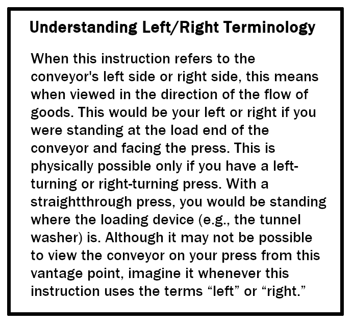
This instruction applies to machines that have taut belt switches (presses manufactured after date
code 04436, with software version 20006D/WUMILSSPA or later)
Adjusting Belt Tracking On the Load End
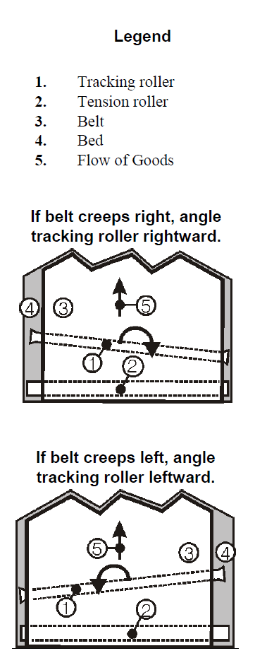
Ideally, the conveyor belt should remain centered on the press bed during operation. Pragmatically, it is likely to creep right or left. The pneumatic tracking system assists in keeping the belt centered. This system consists of a pair of pneumatic switch assemblies (air valve, paddle actuator and hardware) and air cylinders—one set on each side of the belt. When the belt creeps left or right and pushes on a paddle, that air valve opens, actuating the air cylinder, which changes the angle of the tracking roller slightly, moving the belt away from that side of the bed. If the tracking system actuates frequently or cannot successfully center the belt, adjust belt tracking as explained below.
Adjust the tracking as follows:
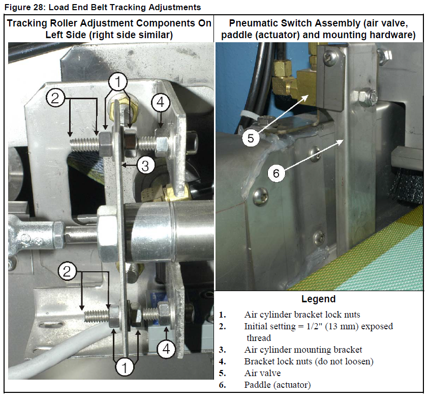
1. Initially, adjust the tracking roller so that it is perpendicular to the press bed. To do so, adjust the air cylinder bracket lock nuts (item 1), on both sides of the conveyor so that there is 1/2"
(13 mm) of thread behind the last lock nut, as shown in item 2.
2. Restore power to the machine.
3. Using Manual mode and selection 10 “Track Belt”, run the belt and observe how it tracks. The belt will tend to track to the looser side.
4. Lockout/tagout power to the machine.
5. To reposition the tracking roller, you will use the air cylinder bracket lock nuts (item 1) to move the air cylinder mounting bracket (item 3) closer to, or farther away from the load end of the conveyor. Do not loosen the adjusting bolt lock nuts (item 4). Use Step 6a or 6b, as appropriate, to adjust the angle of the tracking roller in small increments.
6a. If the belt creeps to the right, make the left side looser, as follows:
1. Adjust the left side air cylinder mounting bracket so it is 1/16" (0.4 mm) farther away from the load end of the conveyor.
2. Adjust the right side air cylinder mounting bracket 1/16" (0.4 mm) closer to the load end.
6b. If the belt creeps to the left, make the right side looser, as follows:
1. Adjust the right side air cylinder mounting bracket 1/16" (0.4 mm) farther away from the load end of the conveyor.
2. Adjust the left side air cylinder mounting bracket 1/16" (0.4 mm) closer to the load end.
7. The pneumatic switches are properly adjusted when the paddles (item 6) are touching the belt and the the air valve (item 5) will open if the belt moves 1/8" (3 mm) closer to the switch. These switches should not need to be removed or adjusted when performing the servicing described herein. However, if this hardware is removed (as to replace components), adjust the switch assemblies as follows:
a. Make sure the belt is precisely centered on the bed.
b. With air on and the assembly mounting bolt loose, move the switch assembly toward the belt just until the air valve opens (as determined by the sound of air flowing), then back the assembly away from the belt 1/8" (3 mm) and tighten the mounting bolt.
Note:
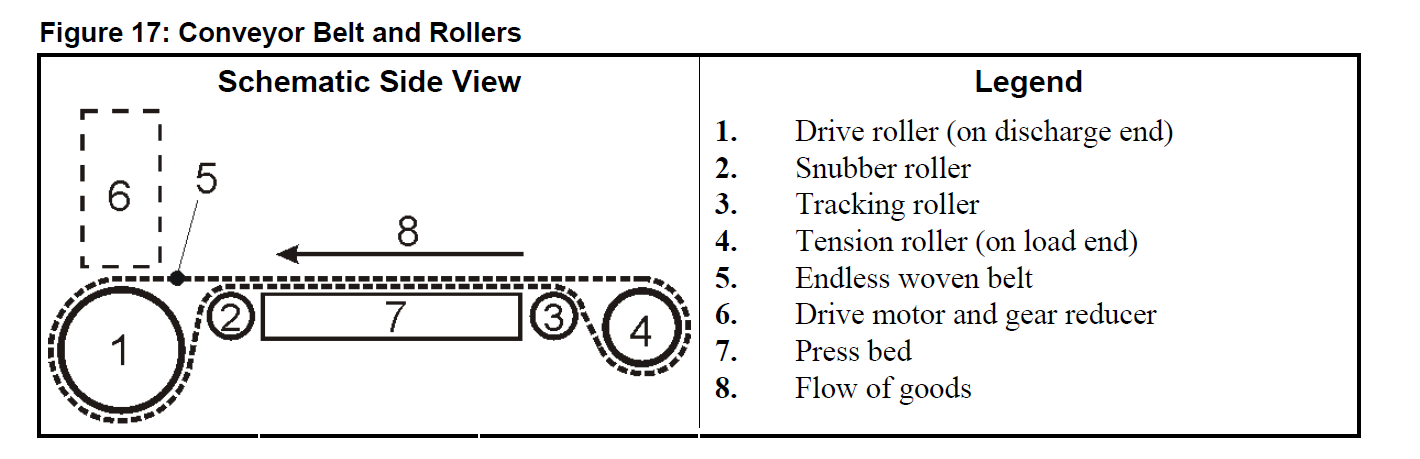
Foreign Material (Goods) Wrapped Around Rollers—If goods wrap around a conveyor roller, this effectively increases the roller diameter. This can severely increase belt tension and the load on the roller bearings. If this condition is addressed soon enough, goods can be cut and unwrapped from the roller fairly easily. But the longer such a problem is left unresolved, the harder it will be to free the roller of the foreign material, and the more likely that the belt and roller bearings will be damaged. Correct the problem when it first arises. Milnor is
not responsible for components damaged through neglect. Referring to Figure 17, goods wrapping is more likely to occur at the drive roller, but it can occur with any of the four rollers. To gain access to the rollers, the technician first removes the tension roller (load end of a straight-in press). Then, on the discharge end (drive roller end) of the machine, he pulls the belt out of the machine, exposing all of the rollers. This procedure is also used in belt replacement.
Restoring Proper Belt Tension
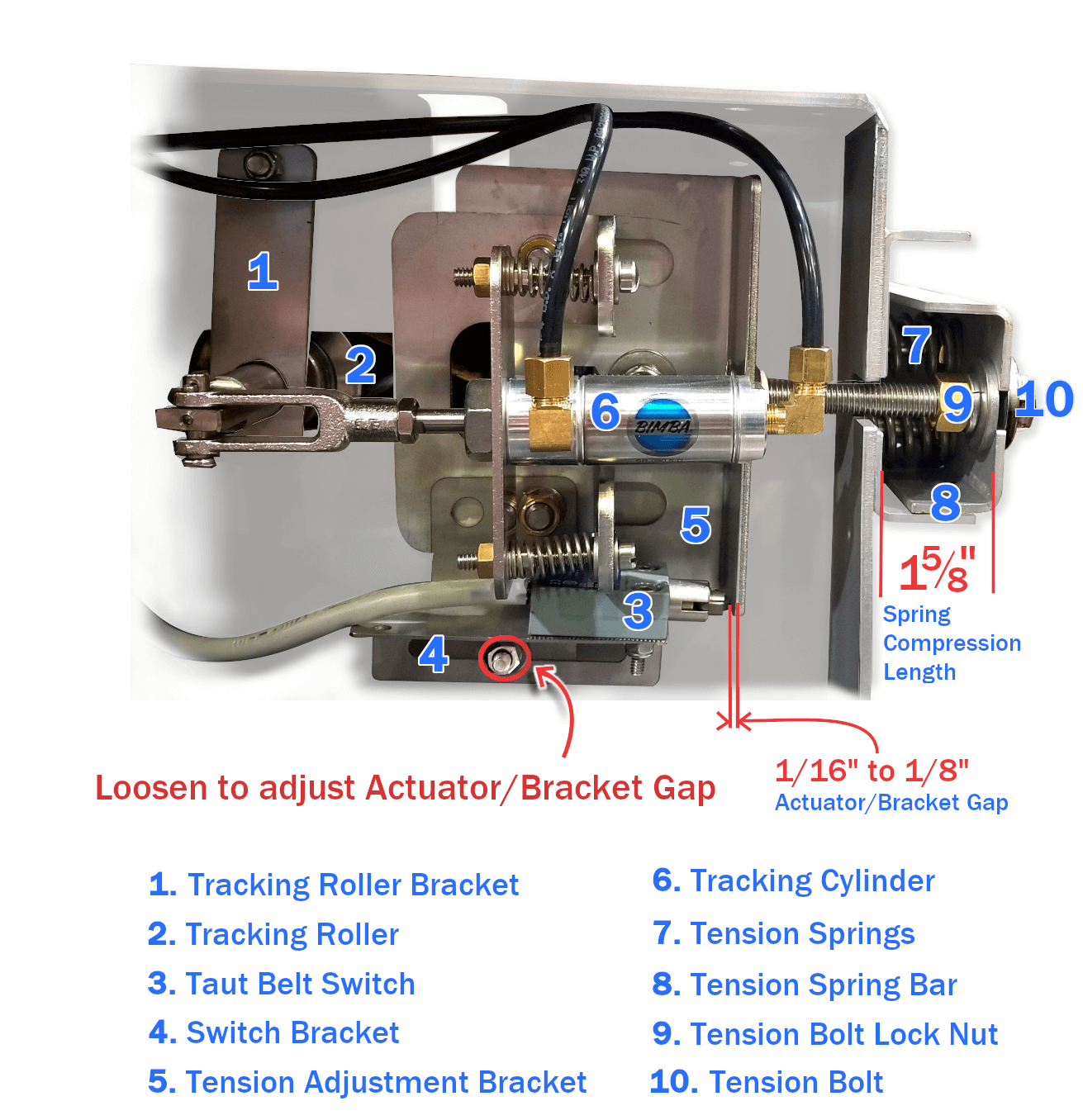
There are two pair of adjustments (each adjustment is done on both sides of the conveyor) involving belt tension. Each adjustment has a required setting (a specified distance between components), as shown in the figure above. Check these measurements and if they have changed, restore them to the required values.
Pre-load—sets the amount of compression of the belt tension springs (belt tension) with no dynamic load on the conveyor. Measure the horizontal distance between the inside faces of the tension bar support channel and tension bar channel. The compressed spring distance should measure 1 5/8" as shown above. This is the compressed spring length. Belt shrinkage will cause this distance to shorten, causing the springs to compress too much. Regaining the specified dimension restores proper belt tension. Make the adjustment by loosening the lock nut
(item 9) and turning the hex tap bolt
(item 10).Taut belt switch clearance—determines the sensitivity of Taut Belt error detection;
it does not control belt tension. Measure the the gap between the bracket and the switch actuator as shown in the image
. This is distance the tension roller must travel before the tension roller bracket touches the
switch actuator. The switch bracket has a slotted mounting hole
(item 4) for adjusting the switch position.
Keywords: single stage press; press belt; taut belt error; limit switch; Bimba air cylinder; belt alignment; loose belt; rollers; tension; 